Ignition device of ignition control system for an internal combustion engine

a technology of ignition control system and ignition device, which is applied in the direction of electric control, ignition automatic control, instruments, etc., can solve the problems of increasing the number of parts of the ignition device, increasing the number of harnesses between the ignition device and the electronic control circuit, and increasing the number of parts of the devi

Active Publication Date: 2008-06-12
MITSUBISHI ELECTRIC CORP
View PDF0 Cites 7 Cited by
  • Summary
  • Abstract
  • Description
  • Claims
  • Application Information

AI Technical Summary

Benefits of technology

[0011]The ignition device of the ignition control system for the internal combustion engine according to the present invention makes it possible to supply an ignition signal...

Problems solved by technology

In the above-mentioned structure, however, the necessity for the dedicated terminal for outputting the failure diagnosis signal causes problems such as an increase in the number of parts of an ignition device and an increase in the number of harnesses between the ignition device and the electronic control circuit.
In a device having this construction as well, similar problems such as an increase in the number of parts of the device and an increase in the number of harnesses are caused when the device is provided with a dedicated terminal for ...

Method used


Image

  • Ignition device of ignition control system for an internal combustion engine
  • Ignition device of ignition control system for an internal combustion engine
  • Ignition device of ignition control system for an internal combustion engine

Examples


first embodiment

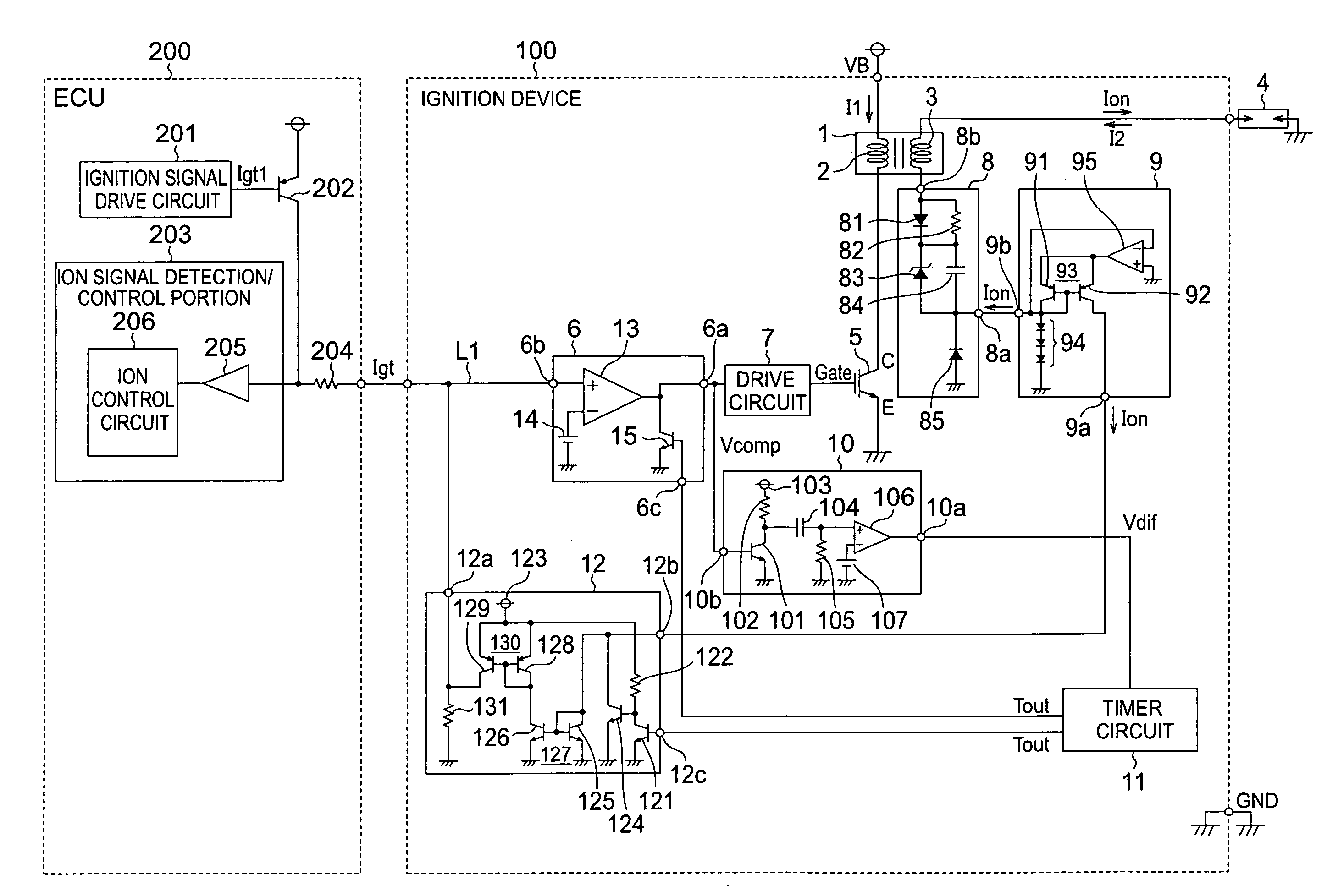
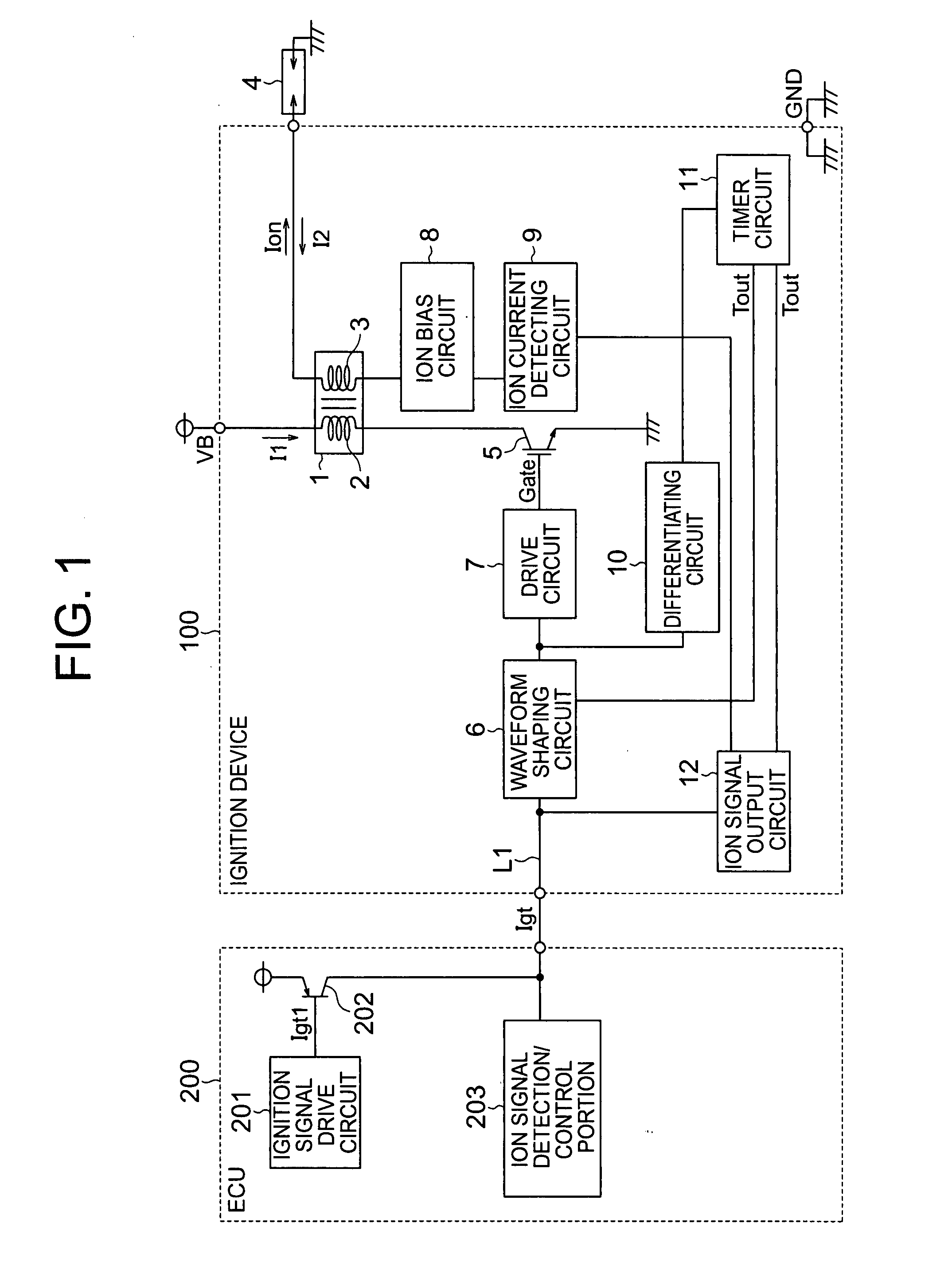
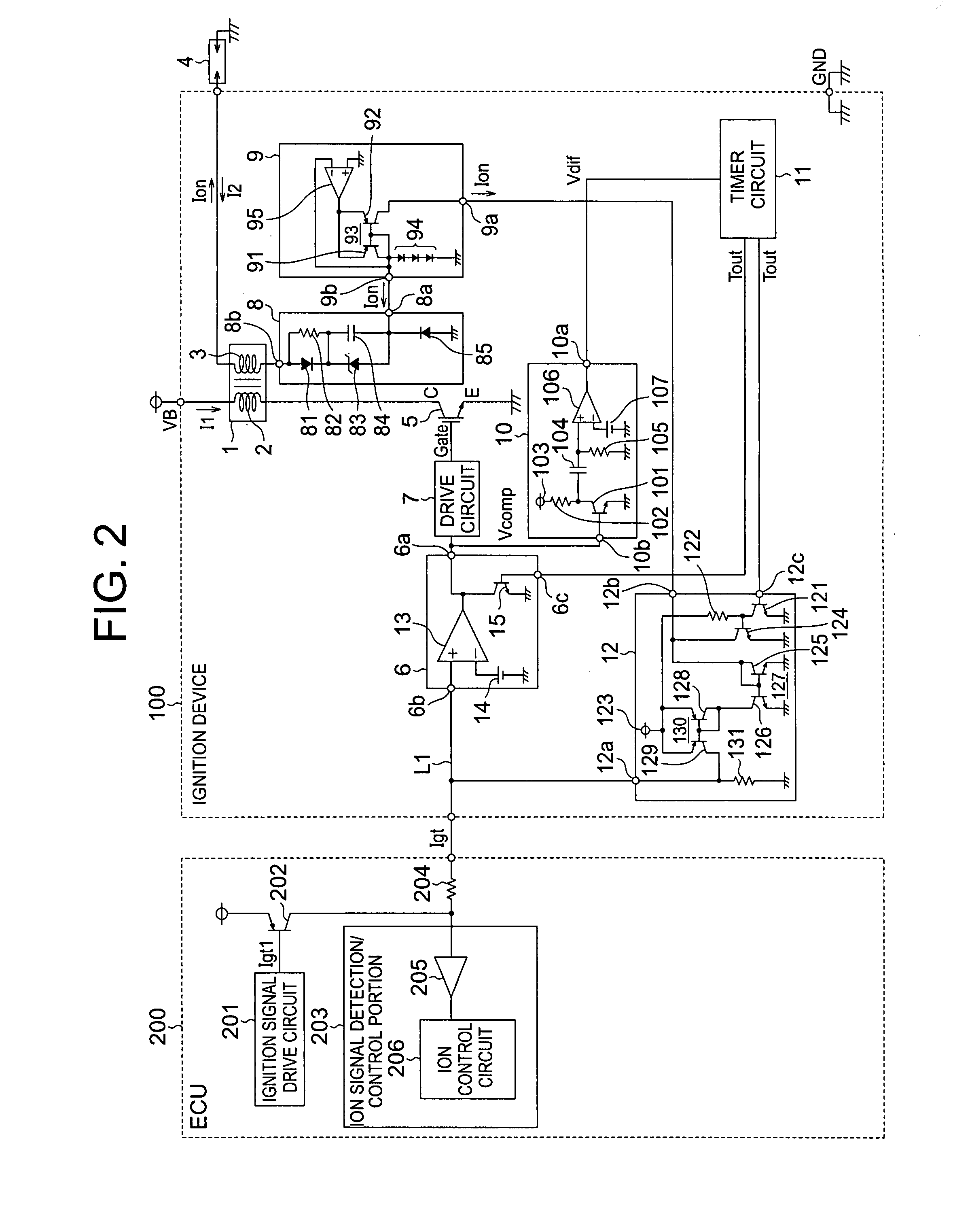
[0022]FIG. 1 is a diagram showing the configuration of an ignition control system for an internal combustion engine including an ignition device according to a first embodiment of the present invention. FIG. 1 shows a circuit for each one of cylinders. This circuit is composed of an ignition device 100 for igniting an ignition plug 4, and an electronic control unit (ECU) 200 including a computer (not shown in particular) for performing ignition control for the ignition device 100.

[0023]The ECU 200 is equipped with an ignition signal drive circuit 201 for supplying an ignition signal, a PNP transistor 202 for supplying a signal to a stage subsequent thereto based on the ignition signal output from the ignition signal drive circuit 201, and an ion signal detection / control portion 203 for detecting an ion signal as a failure diagnosis signal from the later-described ignition device 100 side and performing control based on a result of the detection of the ion signal.

[0024]The ignition d...

second embodiment

[0063]FIG. 5 is a diagram showing the configuration of an ignition control system for an internal combustion engine including an ignition device according to a second embodiment of the present invention. The ignition control system of FIG. 5 is obtained by eliminating the differentiating circuit 10, replacing the ion current detecting circuit 9 with a secondary current and ion current detecting circuit 90, and adding a secondary current pulse circuit 16 in the ignition control system shown in FIG. 1.

[0064]FIG. 6 is a diagram showing an example of the circuitry of respective components of the ignition control system for the internal combustion engine of FIG. 5. In this ignition control system, the secondary current and ion current detecting circuit 90 and the secondary current pulse circuit 16 are used. The second embodiment of the present invention is basically identical to the first embodiment of the present invention in other configurational details. In the second embodiment of th...

third embodiment

[0083]FIG. 8 is a diagram showing the configuration of an ignition control system for an internal combustion engine including an ignition device according to a third embodiment of the present invention. The ignition control system of FIG. 8 is obtained by replacing the timer circuit 11 with a timer circuit 110 in the ignition control system shown in FIG. 6. The third embodiment of the present invention is basically identical to the second embodiment of the present invention in other configurational details. In the third embodiment of the present invention, therefore, the same reference symbols are used to denote the components identical or equivalent to those of the second embodiment of the present invention respectively. The description of those components will be omitted.

[0084]The timer circuit 110 has three terminals, namely, output terminals 11aa and 11bb and an input terminal 11cc. The output terminal 11aa is connected to the input terminal 6c of the waveform shaping circuit 6 ...


PUM


Abstract

An ignition device, including: an ignition coil (1) having a primary coil and a secondary coil; a switching element (5) for causing a primary current to be conducted through and shut off from the primary coil of the ignition coil; a waveform shaping circuit (6) for shaping a waveform of an ignition signal transmitted from an outside through a signal line to supply a conduction signal thus obtained to the switching element; ion current detecting means (8, 9) connected to the secondary coil of the ignition coil, for detecting an ion current flowing through the secondary coil; and ion signal generating means (10, 11, 12) for outputting an ion signal, which indicates the ion current detected for a predetermined period after the conduction signal of the waveform shaping circuit has been turned off, to the outside through the signal line while invalidating the conduction signal from the waveform shaping circuit.

Description

BACKGROUND OF THE INVENTION[0001]1. Field of the Invention[0002]The present invention relates to an ignition control system for an internal combustion engine mounted in, for example, a motor vehicle, and more particularly, to an ignition device of an ignition control system for an internal combustion engine which causes a current to be conducted through and shut off from a primary coil of an ignition coil by means of a switching element to generate a high voltage for ignition in a secondary coil of the ignition coil.[0003]2. Description of the Related Art[0004]In a conventional ignition control system for an internal combustion engine, an ignition device having a coil is provided with a dedicated terminal for outputting a failure diagnosis signal obtained by monitoring an ignition operation, so the failure diagnosis signal is output to an electronic control circuit side through a path different from a path for an ignition signal terminal (e.g., see JP 64-35078 A).[0005]In the above-...

Claims


Application Information

Patent Timeline
IPC IPC(8): F02P5/145
CPCF02D35/021F02D41/221G01L23/225F02P2017/125F02P3/0435
Inventor NARUSE, YUSUKEOKAMURA, KOICHIAIDA, FUTOSHI
Owner MITSUBISHI ELECTRIC CORP
Why Eureka
Try Eureka