
Protective coatings for drill pipe and associated methods

a protection coating and drill pipe technology, applied in the direction of rotary drilling, borehole/well accessories, mechanical equipment, etc., can solve the problems of increasing the cost of exploration and recovery efforts, increasing the difficulty of finding and recovering economic recovery of energy resources such as petroleum and natural gas, and accumulation of debris

Inactive Publication Date: 2008-06-12
AMERICAN CONSULTING TECH
View PDF17 Cites 11 Cited by
  • Summary
  • Abstract
  • Description
  • Claims
  • Application Information

AI Technical Summary

Benefits of technology

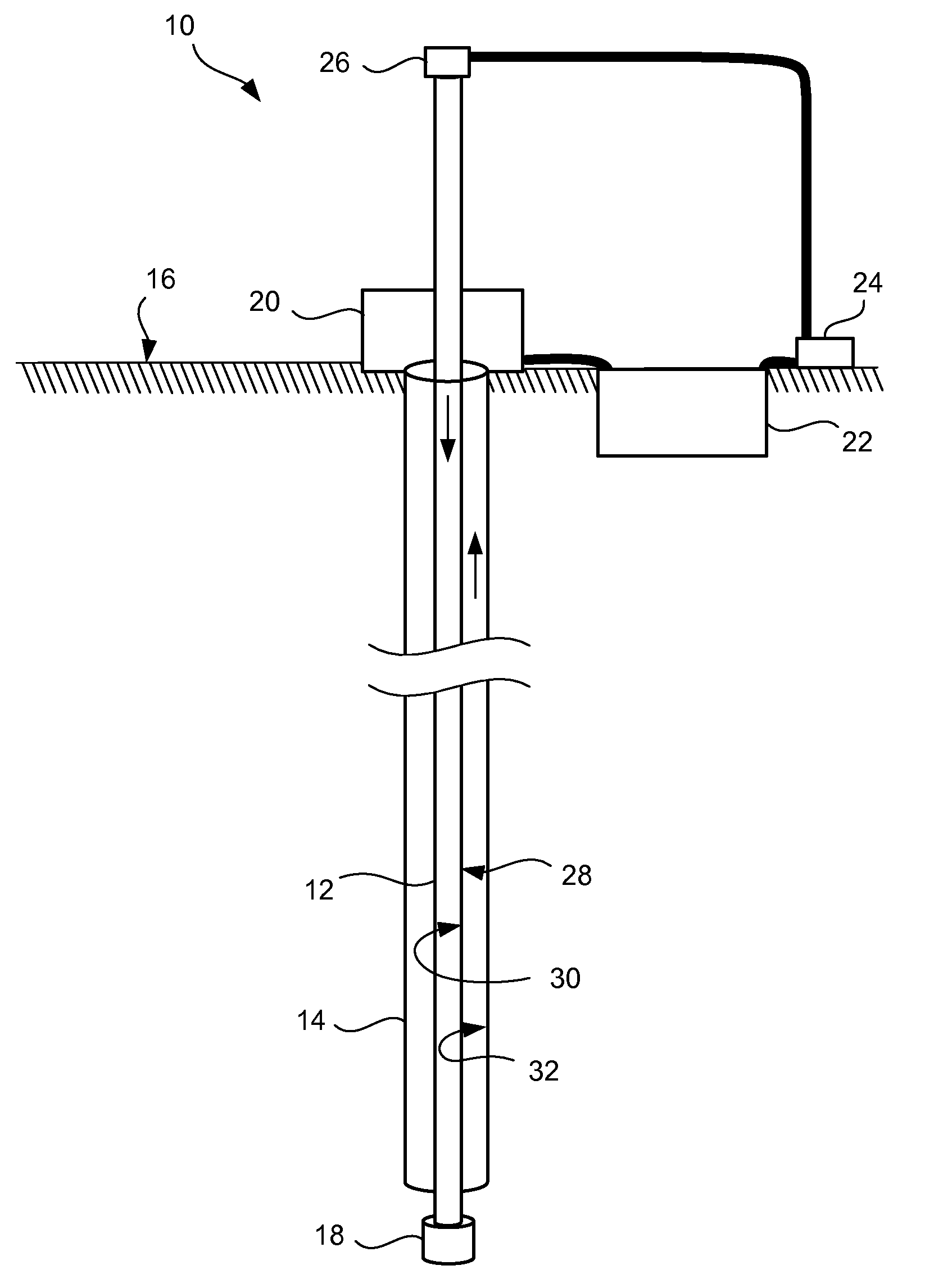
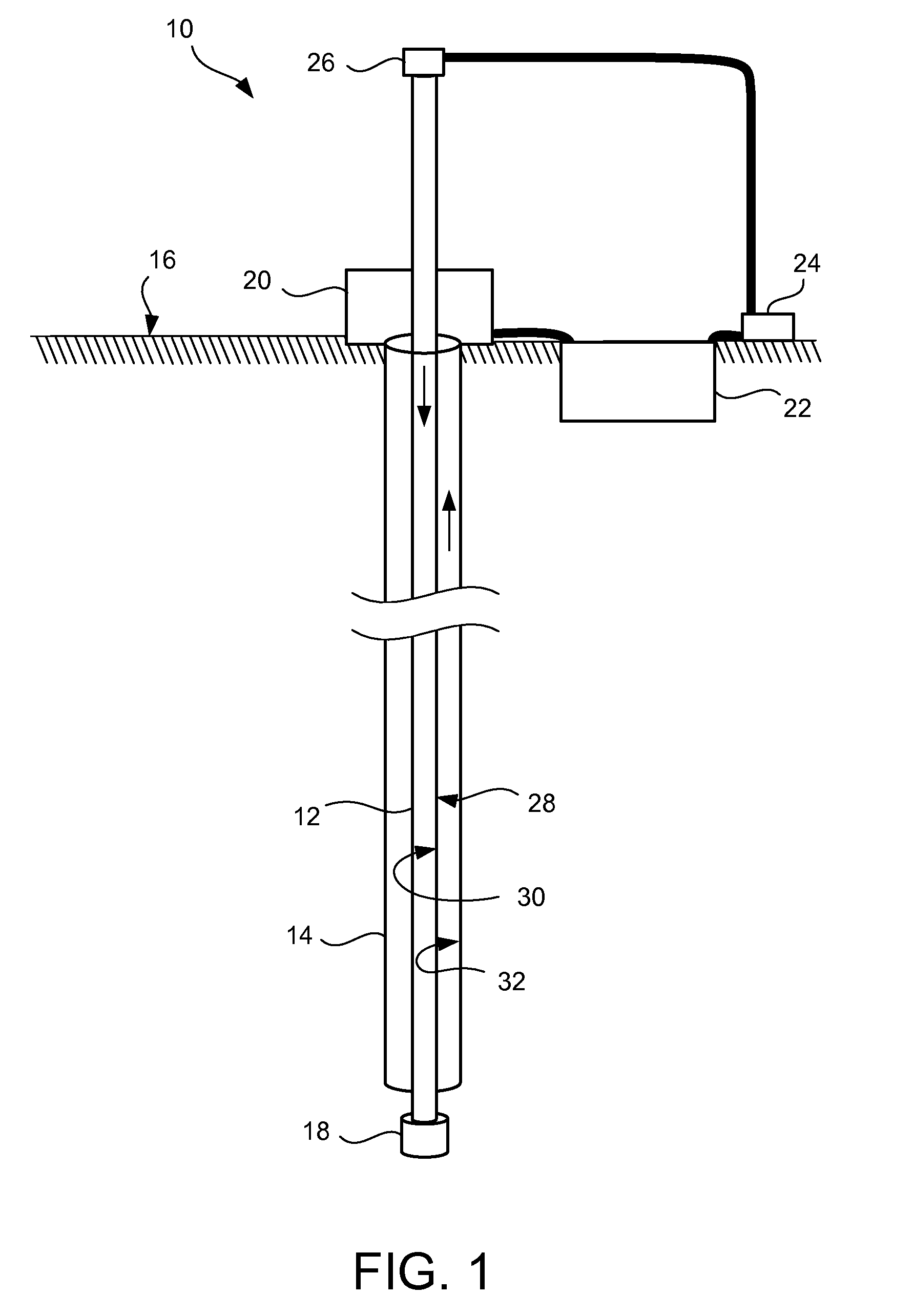
The present invention provides a coated drill pipe for use in ground drilling for explorative geophysics. The drill pipe is coated with a protective coating made of polyurea, which can be applied using spray coating or dip coating methods. The coated drill pipe is then placed inside a well retaining casing that is concentrically oriented around the drill pipe. The coated drill pipe is designed to withstand high levels of mud pressure during drilling operations and can be easily removed from the well. The technical effects of this invention include improved durability and reliability of drill pipes during exploratory drilling operations, reduced risk of damage to the drill pipe, and improved efficiency of drilling operations.

Problems solved by technology

In particular, energy resources such as petroleum and natural gas are becoming increasingly difficult to find and recover economically.
As such the costs of exploration and recovery efforts continue to rise as well.
Unfortunately, during drilling the mud slurry tends to accumulate debris and other materials which become highly corrosive and erosive to the drill pipe and drill shaft of the drill string.
Thus, drill pipes present very unique challenges over conventional transport pipes, sewage pipe, or other pipe.
Although these coatings can be beneficial, improvement in useful life has been limited.
However, these and other approaches still suffer from drawbacks such as limited lifespan, excessive cost, delamination, pin-holes, toxic effluent, among others.

Method used


Image

  • Protective coatings for drill pipe and associated methods
  • Protective coatings for drill pipe and associated methods

Examples


example

[0042]A six inch diameter steel pipe (½″ thickness and 3 feet in length) was obtained from a drilling operation and used as-is without further treatment. A high pressure proportioning pump (available from Grayco Gusmer as Model H2O / 35) with a GX8 Pro gun sprayer was loaded with Evercoat 900 polyurea. The steel pipe was then sprayed along the entire exterior surface with the polyurea to a coating thickness of about 0.05 inches with a gel time about 5 seconds.

[0043]A conventional drill mud (including debris) was circulated past the coated drill pipe under conditions similar to drilling operations, e.g. about 200 rpm for a period of 700 working hours. No detectable change in appearance of the coating could be detected in terms of coloration, surface marring, or delamination.

[0044]The coated drill pipe was then subsequently exposed to a brine solution for a period of another 700 working hours. As before, there was no detectable change in appearance of the coating could be detected in te...


PUM


Abstract

A coated drill pipe for use in drilling ground such as in rotary drilling for explorative geophysics and associated methods and systems are disclosed and described. A protective coating can be coated over at least a portion of an exterior or interior surface of the drill pipe. The protective coating can include a polyurea such as an aromatic polyurea, a silicone modified polyurea, or an aluminized polyurea. Drill pipes can be shielded by coating a drill pipe with a polyurea composition such as by spray coating. In connection with suitable systems and coated or uncoated well casings, these coated drill pipes can perform for dramatically extended periods of time over conventional drill pipes.

Description

RELATED APPLICATIONS[0001]This application claims the benefit of earlier filed U.S. Provisional Patent Application No. 60 / 844,582, filed Sep. 13, 2006 which is incorporated herein by reference.FIELD OF THE INVENTION[0002]The present invention relates generally to drill pipes. More particularly, the present invention is related to methods and associated coatings for rotary drill pipes and the like. Accordingly, the present application involves the fields of geophysics, exploratory drilling, polymer chemistry, and material science.BACKGROUND OF THE INVENTION[0003]Natural resources such as petroleum, natural gas, or other valuable materials often require drilling in order to recover and / or identify. In particular, energy resources such as petroleum and natural gas are becoming increasingly difficult to find and recover economically. As such the costs of exploration and recovery efforts continue to rise as well.[0004]Conventional methods of exploration and recovery include rotary drilli...

Claims


Application Information

Patent Timeline
Patent Type & Authority Applications(United States)
IPC IPC(8): E21B41/00E21B3/00F16L9/14B05D3/00
CPCE21B41/02
Inventor KIPP, MICHAEL D.RIDGES, MICHAELMCCARVILLE, WILLIAM
Owner AMERICAN CONSULTING TECH
Learn More