Method for Controlled Application of a Stator Current Set Point Value and of a Torque Set Point Value for a Converter-Fed Rotating-Field Machine

a technology of stator current and rotating field machine, which is applied in the direction of electric generator control, dynamo-electric converter control, dynamo-electric gear control, etc., can solve the problems of inability to accurately and highly dynamically control the stator current directly, and the efficiency and cost of the inverter are affected

Inactive Publication Date: 2008-06-12
SIEMENS AG
View PDF10 Cites 27 Cited by
  • Summary
  • Abstract
  • Description
  • Claims
  • Application Information

AI Technical Summary

Benefits of technology

[0027]The invention is now based on the object of specifying a method for controlled application of a stator current set point value and of a t

Problems solved by technology

This has a disadvantageous effect on the efficiency and the costs of the inverter.
Traction converters for rail vehicles do not allow high switching frequencies to be used, because of the high power density and the efficiency requirements.
Accurate and highly dynamic control of the stator current has not been possible directly until now because of the considerable harmonics caused by the clocking process and because the machine parameters (straight inductance and main inductance) are highly non-linear for harmonics.
The most important optimization criterion is the root mean square val

Method used


Image

  • Method for Controlled Application of a Stator Current Set Point Value and of a Torque Set Point Value for a Converter-Fed Rotating-Field Machine
  • Method for Controlled Application of a Stator Current Set Point Value and of a Torque Set Point Value for a Converter-Fed Rotating-Field Machine
  • Method for Controlled Application of a Stator Current Set Point Value and of a Torque Set Point Value for a Converter-Fed Rotating-Field Machine

Examples


Embodiment Construction

[0051]In order to ensure clarity, the method according to the invention will be described in the following text using the example of an asynchronous machine.

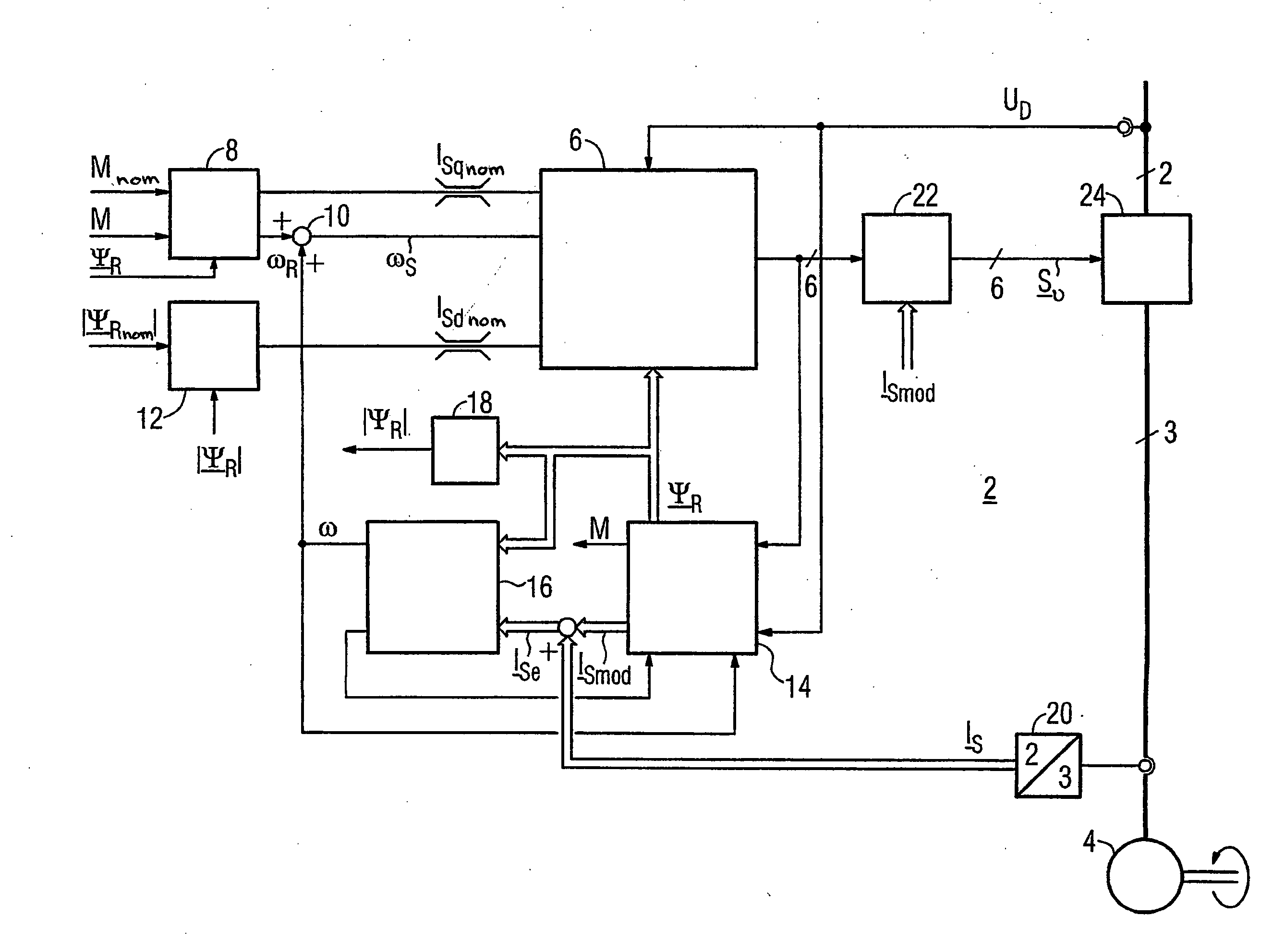
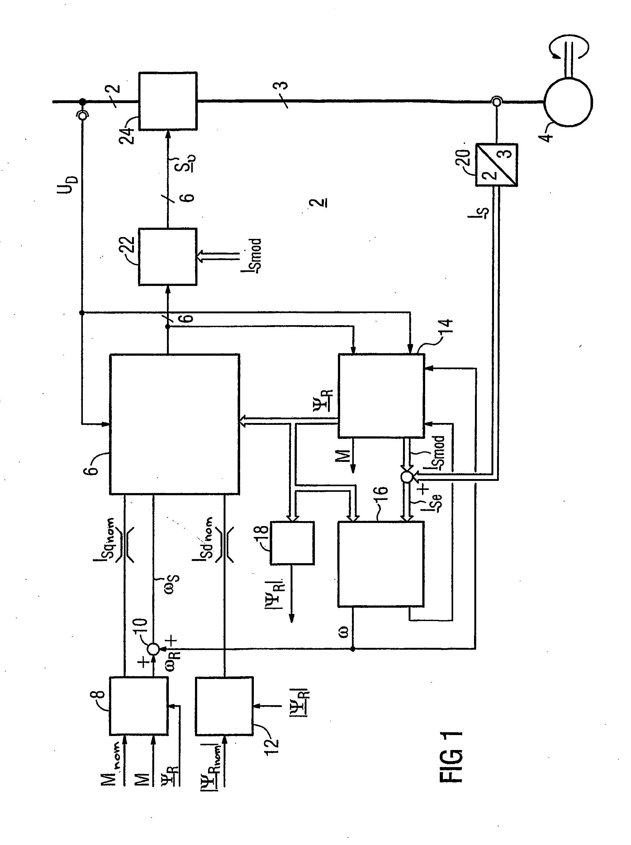
[0052]FIG. 1 shows a structure of the overall drive control 2 for a rotating-field machine 4 without a rotation speed sensor. The device 6, in particular a microprocessor, is responsible for carrying out a major proportion of the method according to the invention. A voltage time integral, which in this case is referred to as the terminal flux ΨKnom, is in this case calculated as a manipulated variable by means of this device 6 from determined current components ISqnom and ISdnom and a determined stator rotation frequency ωS. The torque-forming current component ISqnom of a stator current set point value ISnom to be applied is calculated by means of a torque controller 8 as a function of a torque set point value Mnom, a determined rotor flux actual value ΨR and a torque actual value M. In addition, a rotor slip frequency ωR is pr...


PUM


Abstract

The invention relates to a method for the controlled application of a stator-current target value (ISnom) and a torque target value (Mnom) for a polyphase machine (4) that is supplied by an electronic power converter. According to the invention: current components (ISdnom, ISqnom) in a co-ordinate system (d, q) with a fixed rotor flux or rotating magnetic pole are calculated in accordance with a torque target value and in asynchronous machines in accordance with a rotor-flux target value (ΨRnom), a calculated rotor-flux actual value (Ψ<SB>R</SB>) or a rotating magnetic-pole flux; a stator-circuit frequency (ω<SB>S</SB>) is determined; a terminal-flux target value (ΨKnom) is calculated in accordance with the values (ISnom, ISqnom, Ψ<SB>R</SB>, ω<SB>S</SB>) by means of the machine parameters (L, R<SB>S</SB>), said terminal-flux target value being subsequently projected onto a flux-course curve, selected from stored, off-line optimised flux-course curves. This permits the state of the stator current (I<SB>S</SB>) to be regulated in relation to the rotor flux (Ψ<SB>R</SB>) or rotating magnetic-pole flux by means of momentary values, facilitating a stationary and dynamic precise control of motor currents (I1,I2,I3) and thus the torques (M) of a polyphase machine (4).

Description

BACKGROUND OF THE INVENTION[0001]The invention relates to a method for controlled application of a stator current set point value and of a torque set point value for a converter-fed rotating-field machine.[0002]Pulse-controlled inverters with a constant input voltage are frequently used in conjunction with a field-oriented control method in order to feed rotating-field machines whose torque can be varied in a highly dynamic form to desired values within a wide rotation speed range. A drive system such as this is normally also adequate to satisfy very stringent technical demands for the control quality. Subject to the precondition of terminal currents which can be applied in any desired manner, the magnetic flux and the torque of a rotating-field machine can in principle be set continuously variably to desired values, although only if all of the electromagnetic system parameters of a sufficiently accurate description model of the machine are known. The associated terminal voltages ca...

Claims


Application Information

Patent Timeline
IPC IPC(8): H02P21/08H02P21/12H02P23/00H02P27/12
CPCH02P21/005H02P27/12H02P23/004H02P21/12H02P21/30H02P23/30
Inventor HOFFMANN, FRANKSPERR, FRANZSTANKE, GEORG
Owner SIEMENS AG
Why Eureka
Try Eureka