Projection display

Inactive Publication Date: 2008-06-12
MITSUBISHI ELECTRIC CORP
View PDF2 Cites 22 Cited by
  • Summary
  • Abstract
  • Description
  • Claims
  • Application Information

AI Technical Summary

Benefits of technology

[0014]It is a first object of the present invention to provide a projection display whose maximum lum

Problems solved by technology

In order to raise the maximum luminance, there is a method that increases the amount of light of the light source, but when the amount of light of the light source is increased, the maximum luminance rises but the minimum luminance also rises at the same time, so the contrast ratio is not improved.
Further, the power consumption of the light source also becomes larger and, as a result, there is the problem that the lifespan of the light source becomes shorter.
Thus, simply increasing the amount of light of the light source is not a good solution.
However, the increase in cost resulting from the iris diaphragm and a motor for driving the iris diaphragm has become a large problem.
Further, although this method should be capable of dimming 0 to 100% because it mechanically adjusts the aperture, uniformity in the luminance on the screen becomes poor when the area th

Method used


Image

  • Projection display
  • Projection display
  • Projection display

Examples


first exemplary embodiment

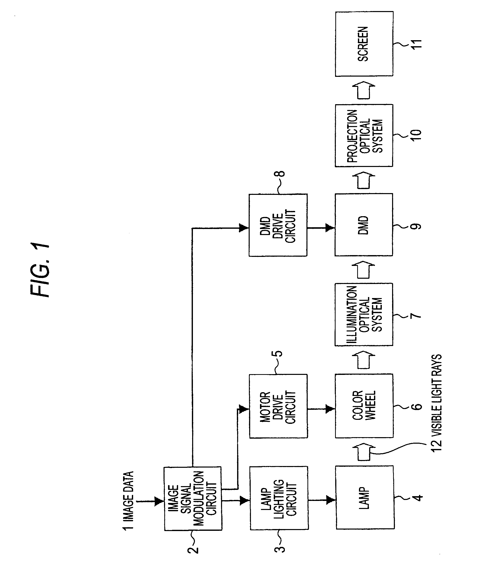
[0035]FIG. 1 is a system diagram of a projection display in a first exemplary embodiment of the present invention. In the present exemplary embodiment, a Digital Light Processing (DLP, registered trademark of Texas Instruments, Inc.) projection display will be described as the projection display. A DLP is a projection display that uses a DMD as a light modulating device.

[0036]In FIG. 1, an image signal modulation circuit 2 modulates inputted image data 1, sends the data to a DMD drive circuit 8, and also sends a synchronizing signal to a lamp lighting circuit 3 and a motor drive circuit 5.

[0037]The lamp lighting circuit 3 inputs a later-described specific power waveform to a lamp 4 serving as a light source to cause the lamp 4 to radiate visible light rays 12. The lamp 4 is, for example, an ultra high pressure mercury lamp, which is an HID lamp.

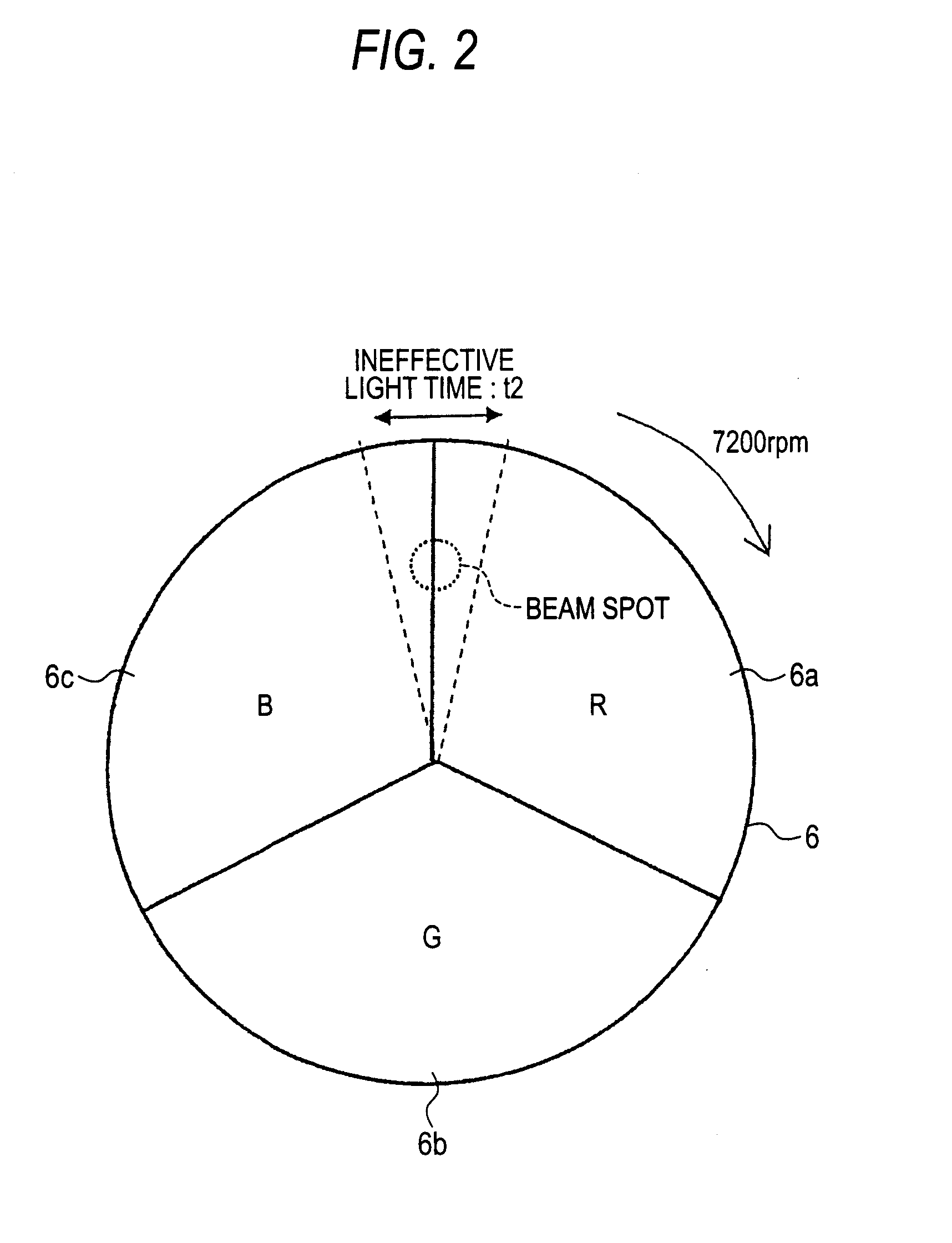
[0038]As shown in FIG. 2, a color wheel 6 is configured by a red transmission filter 6a, a green transmission filter 6b, and a blue transmis...

second exemplary embodiment

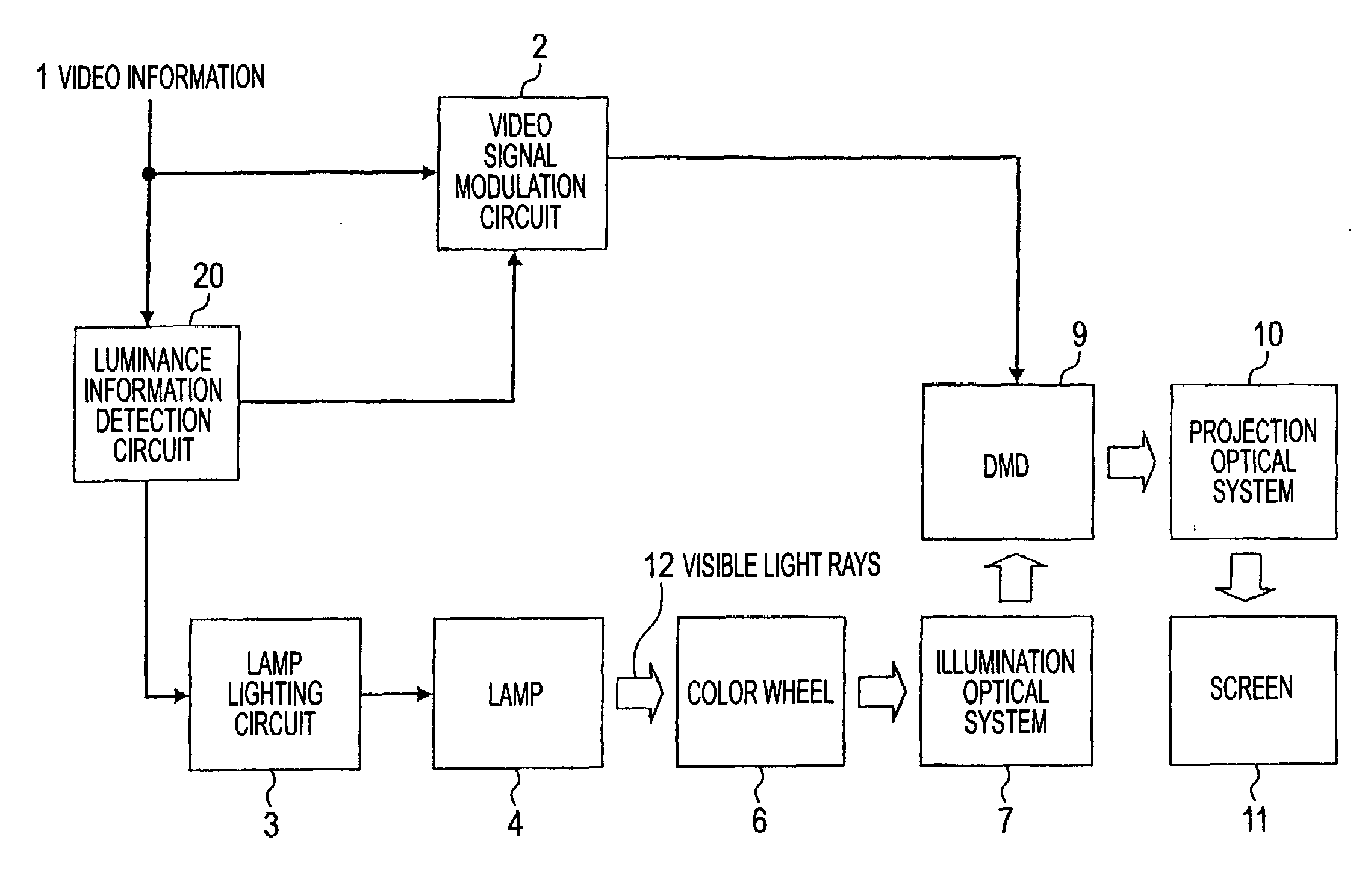
[0056]FIG. 5 shows a system configuration diagram of a projection display in a second exemplary embodiment of this invention, and the same reference numerals except 1 and 2 show portions that are the same as those in FIG. 1. What is different from the first exemplary embodiment is that here the projection display includes a luminance information detection circuit 20 that extracts luminance information from video information 1, and the luminance information detection circuit 20 outputs this luminance signal to a video signal modulation circuit 2 and the lamp lighting circuit 3. It will be noted that illustration of the motor drive circuit 5 that is driven in accordance with a synchronizing signal from the video signal modulation circuit 2 is omitted. The luminance information detection circuit 20 detects characteristics of luminance information on the basis of the video information 1 inputted from video information inputting means (not shown), digitalizes the characteristics as lumin...

third exemplary embodiment

[0070]In the second exemplary embodiment, the power P1 is adjusted under the condition that the average power is constant in order to keep the temperature of the lamp at a constant. Incidentally, as long as the temperature of the lamp is within the use temperature range of the lamp, the halogen cycle works appropriately even if the average power is changed somewhat, so the lifespan of the lamp is not adversely affected. In the lamp with a rating of 150 W described here, the average power that can be adjusted without going out of the use temperature range of the lamp was 110 W to 190 W. In the third exemplary embodiment, instead of the control described in the second exemplary embodiment that keeps the average power at a constant, means that adjusts the power P1 by changing the average power in a range where the halogen cycle of the lamp is appropriately conducted—that is, in the use temperature range of the lamp—will be described.

[0071]In FIG. 11, the bold solid line represents the ...


PUM


Abstract

A projection display uses a light modulating device to modulate, in accordance with image data, light radiated from a light source, project the modulated light onto a screen, and display an image. The projection display separates a unit of time configuring the image data into an effective light time when the light modulating device can express the light as an image on the screen and an ineffective light time when the light modulating device cannot express the light as an image on the screen. The projection display increases the power supplied to the light source during the effective light time over the power supplied to the light source during the ineffective light time.

Description

BACKGROUND OF THE INVENTION[0001]1. Field of the Invention[0002]The present invention relates to a projection display that uses a light modulating device.[0003]2. Description of the Related Art[0004]There are projection displays that use a light modulating device such as a liquid crystal display (LCD) or a digital micromirror device (DMD) to modulate, in accordance with image data, light radiated from a light source, project the modulated light onto a screen, and display an image.[0005]For example, a projection display using a DMD such as described in JP-A No. 2003-102030 expresses shades of gray of image information by switching the inclination of the mirrors of the DMD—that is, the reflectance on the screen—in accordance with the image information. The reflectance of the DMD on the screen takes two values: an ON state where the mirrors reflect light onto the screen and an OFF state where the mirrors do not reflect light onto the screen. The light projected onto the screen in the O...

Claims


Application Information

Patent Timeline
IPC IPC(8): H04N5/74
CPCH04N9/312H05B41/2928H04N9/3197H04N9/3155
Inventor HARADA, SHIGEKINAGAI, TAKAYOSHISUGA, IKUROIWATA, AKIHIKOSUZUKI, YOSHITERUOKUMURA, AKIRASOMEYA, JUNKOJIMA, KUNIKO
Owner MITSUBISHI ELECTRIC CORP
Why Eureka
Try Eureka