AI technical title is built by Patsnap AI team. It summarizes the technical point description of the patent document.
a technology of lighting fixtures and lamps, applied in the field of lighting fixtures, can solve the problems of undesired heating of fixtures, waste of electrical energy, and excessive amount of light emitted by lamps, and achieve the effects of facilitating the shaping of any selected part, enhancing the quality of the projected beam of light, and reducing the heat radiated from the front of lamps
Inactive Publication Date: 2008-06-12
WIMBERLY RANDAL LEE
View PDF8 Cites 42 Cited by
Summary
Abstract
Description
Claims
Application Information
AI Technical Summary
This helps you quickly interpret patents by identifying the three key elements:
Problems solved by technology
Method used
Benefits of technology
Benefits of technology
[0010]Objects of the invention are to provide a lighting fixture for use in combination with a lamp in imaging a beam of light at a distant location, while utilizing a substantially greater proportion of visible light emitted by the lamp. An alternative embodiment of the fixture projects a substantially lower proportion of infrared light emitted by the lamp. Additionally the lighting fixture may be configured to have two lenses including a convenient method of adjustment to focus the beam of light at a distant location and, providing a variable beam spread and a variable image distance. A substantially more efficient lighting fixture thereby is provided.
Problems solved by technology
Another problem commonly encountered by lighting fixtures of this kind is that an excessive amount of light emitted by the lamp is not incorporated into the projected beam, but instead is misdirected and absorbed by the shutters, patterns, gate and other internal components of the fixture.
This wastes electrical energy and leads to undesired heating of the fixture.
In many instances, the shutters and patterns can be warped by the excessive heat and therefore need to be frequently replaced.
Another problem encountered in lighting fixtures of this kind is that the imaged light beam can sometimes have an intensity that varies such that a concentric ring pattern, or circular pattern with intense center, or oval pattern with intense longitudinal bars, or a pattern with four intense points of light energy is provided.
This undesired pattern occurs because of the particular kind of filament used in the lamp, e.g., a coiled coil, biplane, or four pole longitudinal.
Although such a reflector structure is generally effective in diminishing this effect, it is believed that this solution misdirects an excessive amount of light so as not to be incorporated into the projected beam.
Another drawback to lighting fixtures of the kind described above is that the fixture projects an undesired amount of infrared light along with the desired visible light.
This unduly heats the area on which the projected light is imaged, which in the case of theater, television and some architectural lighting can lead to substantial discomfort.
Reflecting undesired infrared light also leads to undesired heating of the pattern and shutters located at the gate and of any colored media or gels located forwardly of the lens.
In some cases, highly absorptive media, such as blue gels, burn out very quickly or cannot be used at all.
In other cases, lens made of plastic will melt or disfigure and become useless.
Method used
Image
Click on the blue label to locate the original text in one second.
Reading with bidirectional positioning of images and text.
Examples
Embodiment Construction
[0030]Reference will now be made in detail to the present preferred embodiment of the invention, examples of which are illustrated by the accompanying drawings. While the invention will be described in connection with a preferred embodiment, it will be understood that it is not intended to limit the invention to that embodiment.
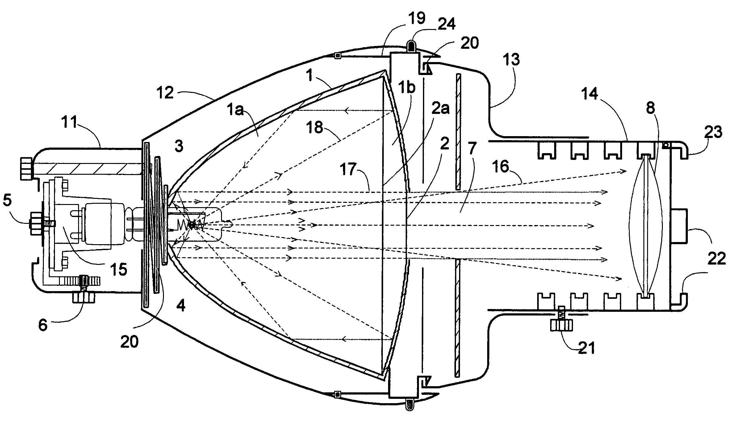
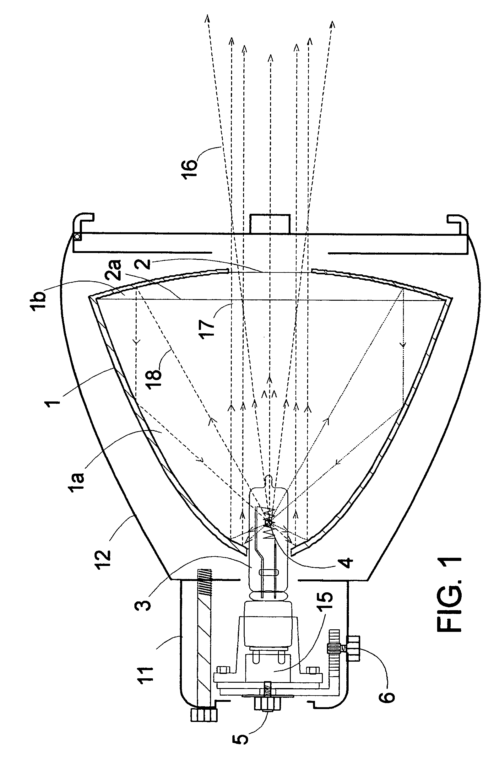
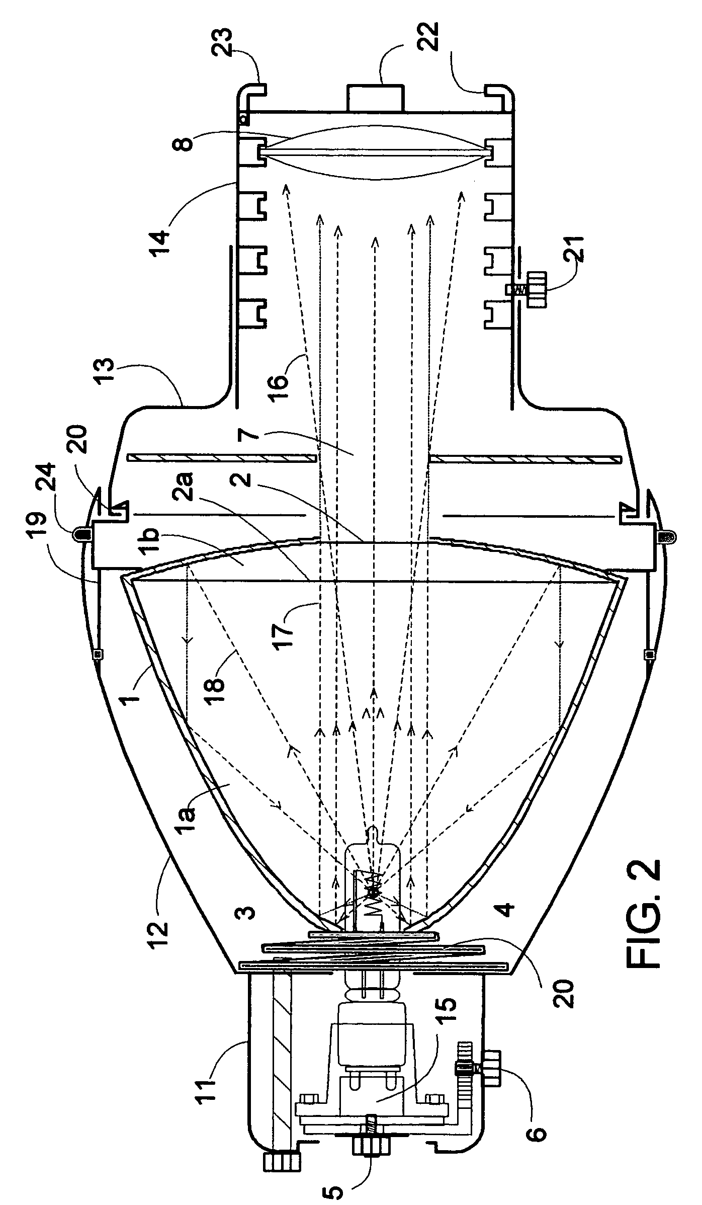
[0031]FIG. 1 is a schematic diagram of a first embodiment of a lighting fixture in accordance with the invention. The fixture includes a compound concave duel parabolic reflectorsystem 1 having a rear reflector part 1a with a deep substantially parabolic curve shape and a forward reflector part 1b shaped as a zone of a shallow substantially parabolic curve having a larger parallel edge 2a and a smaller parallel edge, said smaller edge serving as an aperture 2, and said larger parallel edge 2a connected to said rear parabolic reflector part 1a such that the focal point 4 of said forward parabolic reflector part 1b is also said first focus 4 of said rear parab...
PUM
Property
Measurement
Unit
Length
aaaaa
aaaaa
Electrical resistance
aaaaa
aaaaa
Radius
aaaaa
aaaaa
Abstract
An improved lighting fixture is disclosed for imaging a high-intensity beam of light at a distant location. A specially-made duel parabolic reflectorsystem cooperates with a gate aperture and a single aspheric lens to produce a beam that incorporates a very high proportion of emitted visible light. Alternatively, said fixture has two lenses in a positioning mechanism mounted in the housing, and includes a rack and pinion gear device that adjusts the distance between the front and rear lenses in response to the rotation of an actuator. The actuator is configured to slide along a slot in the housing, controlling the translation of the first and second lenses with respect to the gate aperture. A shielding baffle covers the slot. The actuator is further configured with a locking mechanism that constrains the actuator from being moved with respect to the housing when the locking mechanism is in position. Additionally the rear parabolic reflector part has a dichroich coating that reflects only a low proportion of infrared light. The projected beam thereby has a relatively low energy density, such that the front portion of the fixture can be reduced substantially in size, be made of light weight materials with lower temperature resistance, and utilize lenses made of plastic. The gate is selectively rotatable relative to the fixture's rear housing.
Description
[0001]REFERENCES CITED:U.S. Pat. No. 1,742,600January 1930Kliegl et al.U.S. Pat. No. 1,595,533August 1925WeemsU.S. Pat. No. 2,650,292August 1953StrongU.S. Pat. No. 3,662,165May 1972Osteen et al.U.S. Pat. No. 3,704,928December 1972Coombs et al.U.S. Pat. No. 3,883,733May 1975NagelU.S. Pat. No. 3,930,149December 1975FrenchU.S. Pat. No. 4,187,534February 1980Tichenor et al.U.S. Pat. No. 4,240,133December 1980Haina et al.U.S. Pat. No. 4,462,067July 1984AltmanU.S. Pat. No. 4,517,630May 1985Dieffenbach et al.U.S. Pat. No. 4,519,021May 1985OramU.S. Pat. No. 4,545,000October 1985Fraley et al.U.S. Pat. No. 4,609,976September 1986GeisslerU.S. Pat. No. 5,160,192November 1992SugawaraU.S. Pat. No. 5,345,371September 1994Cunningham et al.U.S. Pat. No. 5,544,029August 1996CunninghamU.S. Pat. No. 6,092,914Jul. 25, 2000Esakoff, et al.U.S. Patent ApplicationWimberlyS.N. 10 / 577,580.TECHNICAL FIELD[0002]The present invention is in the field of lighting fixtures and, more particularly, to lighting fixtur...
Claims
Application Information
Patent Timeline
Application Date:The date an application was filed.
Publication Date:The date a patent or application was officially published.
First Publication Date:The earliest publication date of a patent with the same application number.
Issue Date:Publication date of the patent grant document.
PCT Entry Date:The Entry date of PCT National Phase.
Estimated Expiry Date:The statutory expiry date of a patent right according to the Patent Law, and it is the longest term of protection that the patent right can achieve without the termination of the patent right due to other reasons(Term extension factor has been taken into account ).
Invalid Date:Actual expiry date is based on effective date or publication date of legal transaction data of invalid patent.

