
Utility function execution using scout threads

a technology of utility functions and threads, applied in the field of multi-threaded processing systems, can solve the problems of increasing complexity and overhead, less effective for various types of code, and prone to prefetching excessive overhead, so as to improve the performance of the main thread

Inactive Publication Date: 2008-06-12
SUN MICROSYSTEMS INC
View PDF29 Cites 30 Cited by
  • Summary
  • Abstract
  • Description
  • Claims
  • Application Information

AI Technical Summary

Benefits of technology

[0009]A method is contemplated wherein a scout thread is utilized in a second core or logical processor in a multi-threaded system to improve the performance of a main thread. In one embodiment, a scout thread executes in parallel with the main thread that it attempts to accelerate. The scout and main threads are configured to operate in a producer-consumer relationship. The scout thread is configured to execute utility type functions in advance of the main thread reaching such functions in the program code. The scout thread executes in parallel with the first thread and produces results from the execution which are made available for consu...

Problems solved by technology

Although such prefetching may be successful for many cases, it may be less effective for various types of code.
Prefetching in such code tends to incur excessive overhead as significant computation is required to compute future addresses.
The complexity and overhead may also increase if the subscript evaluation involves loads that themselves must be prefetched and made speculative.
If the prefetched data is already in the cache, such large overheads can cause a significant slowdown.
Interleaved prefetching is generally not able to handle such cases.
While a variety of approaches have been proposed to attack pointer-chasing, none have been entirely successful.
In addition to the above, it can be very difficult to parallelize single threaded program code.
In such cases it may be difficult to fully utilize a multithreaded processor and processor resources may go unused.

Method used


Image

  • Utility function execution using scout threads
  • Utility function execution using scout threads
  • Utility function execution using scout threads

Examples


Embodiment Construction

Overview of Multithreaded Processor Architecture

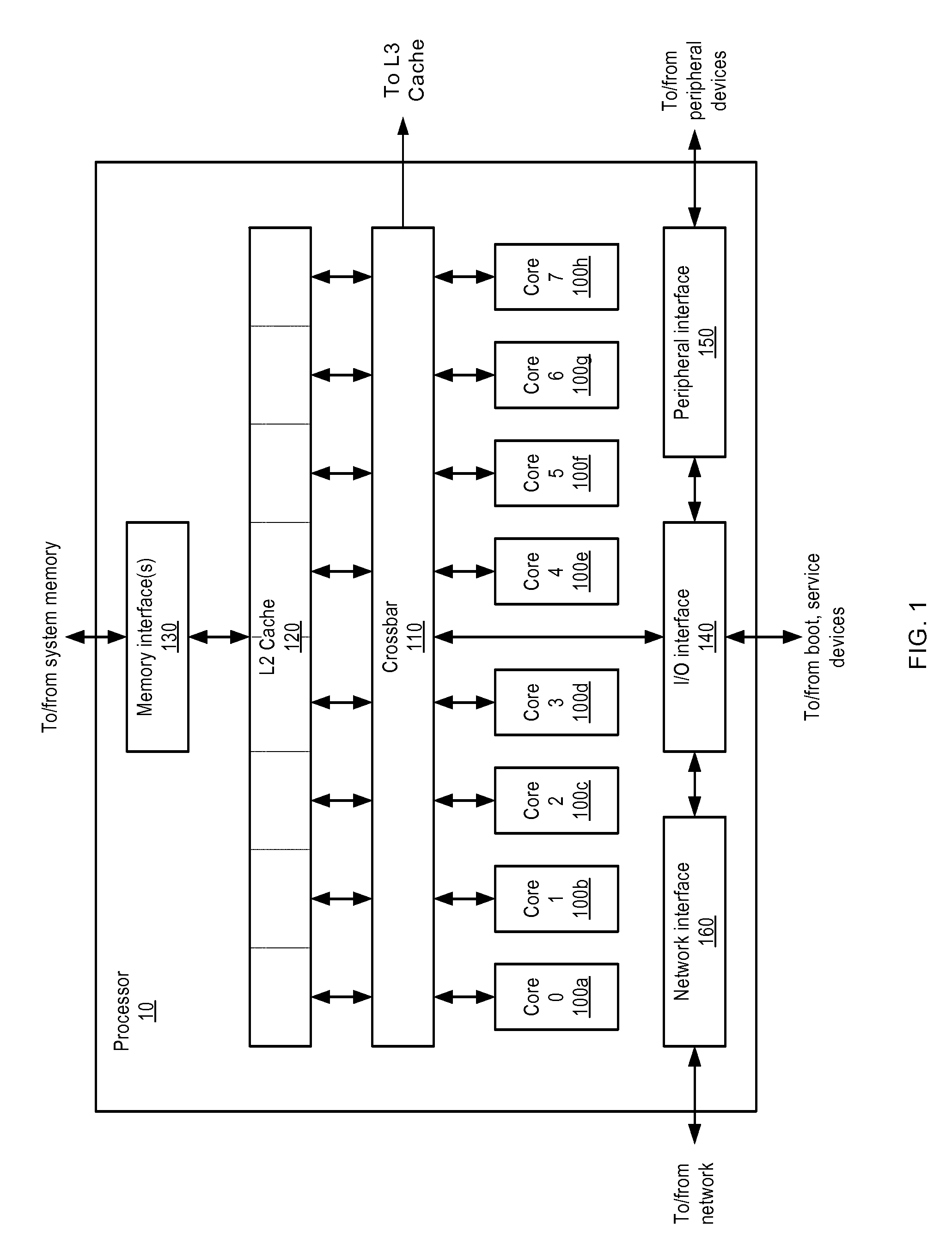
[0021]A block diagram illustrating one embodiment of a multithreaded processor 10 is shown in FIG. 1. In the illustrated embodiment, processor 10 includes a plurality of processor cores 100a-h, which are also designated “core 0” though “core 7”. Each of cores 100 is coupled to an L2 cache 120 via a crossbar 110. L2 cache 120 is coupled to one or more memory interface(s) 130, which are coupled in turn to one or more banks of system memory (not shown). Additionally, crossbar 110 couples cores 100 to input / output (I / O) interface 140, which is in turn coupled to a peripheral interface 150 and a network interface 160. As described in greater detail below, I / O interface 140, peripheral interface 150, and network interface 160 may respectively couple processor 10 to boot and / or service devices, peripheral devices, and a network.

[0022]Cores 100 may be configured to execute instructions and to process data according to a particular instruction ...


PUM


Abstract

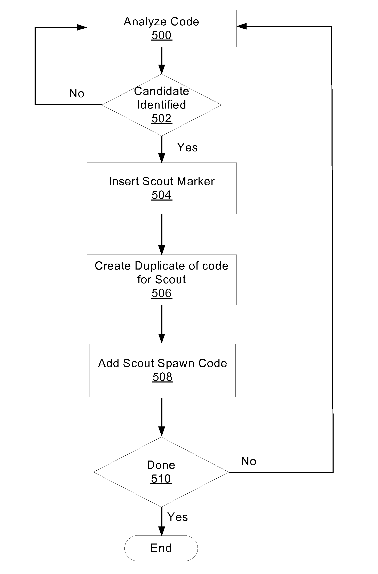
A method and mechanism for using threads in a computing system. A multithreaded computing system is configured to execute a first thread and a second thread. The first and second threads are configured to operate in a producer-consumer relationship. The second thread is configured to execute utility type functions in advance of the first thread reaching the functions in the program code. The second thread executes in parallel with the first thread and produces results from the execution which are made available for consumption by the first thread. Analysis of the program code is performed to identify such utility functions and modify the program code to support execution of the functions by the second thread.

Description

BACKGROUND OF THE INVENTION[0001]1. Field of the Invention[0002]The invention relates to computing systems and, more particularly, to multithreaded processing systems.[0003]2. Description of the Related Art[0004]With the widening gap between processor and memory speeds, various techniques have arisen to improve application performance. One technique utilized to attempt to improve computing performance involves using “helper” or “scout” threads. Generally speaking, a helper thread is a thread which is used to assist, or improve, the performance of a main thread. For example, a helper thread may be used to prefetch data into a cache. For example, such approaches are described in Yonghong Song, Spiros Kalogeropulos, Partha Tirumalai, “Design and Implementation of a Compiler Framework for Helper Threading on Multi-core Processors,” pp. 99-109, 14th International Conference on Parallel Architectures and Compilation Techniques (PACT'05), 2005, the content of which is incorporated herein b...

Claims


Application Information

Patent Timeline
IPC IPC(8): G06F9/46
CPCG06F9/4843
Inventor TIRUMALAI, PARTHA P.SONG, YONGHONGKALOGEROPULOS, SPIROS
Owner SUN MICROSYSTEMS INC
Learn More