Electron emission light-emitting device and light emitting method thereof

Active Publication Date: 2008-06-19
IND TECH RES INST
View PDF11 Cites 4 Cited by
  • Summary
  • Abstract
  • Description
  • Claims
  • Application Information

AI Technical Summary

Benefits of technology

[0016]In view of the above, the present invention uses a thin gas to easily induce electrons from the cathode, thus avoiding possible problems resulting from fabricating the electron emitter on the cathode. Moreover, as the gas is thin, the electrons have a large mean free path allow

Problems solved by technology

However, the above two types of light-emitting structures have disadvantages.
On the other hand, the field emission light source requires a uniform electron emitter to be grown or coated on the cathode, but the mass production technique of this type of cathode structure is not mature, and the uni

Method used


Image

  • Electron emission light-emitting device and light emitting method thereof
  • Electron emission light-emitting device and light emitting method thereof
  • Electron emission light-emitting device and light emitting method thereof

Examples


Embodiment Construction

[0026]Reference will now be made in detail to the present embodiments of the invention, examples of which are illustrated in the accompanying drawings. Wherever possible, the same reference numbers are used in the drawings and the description to refer to the same or like parts.

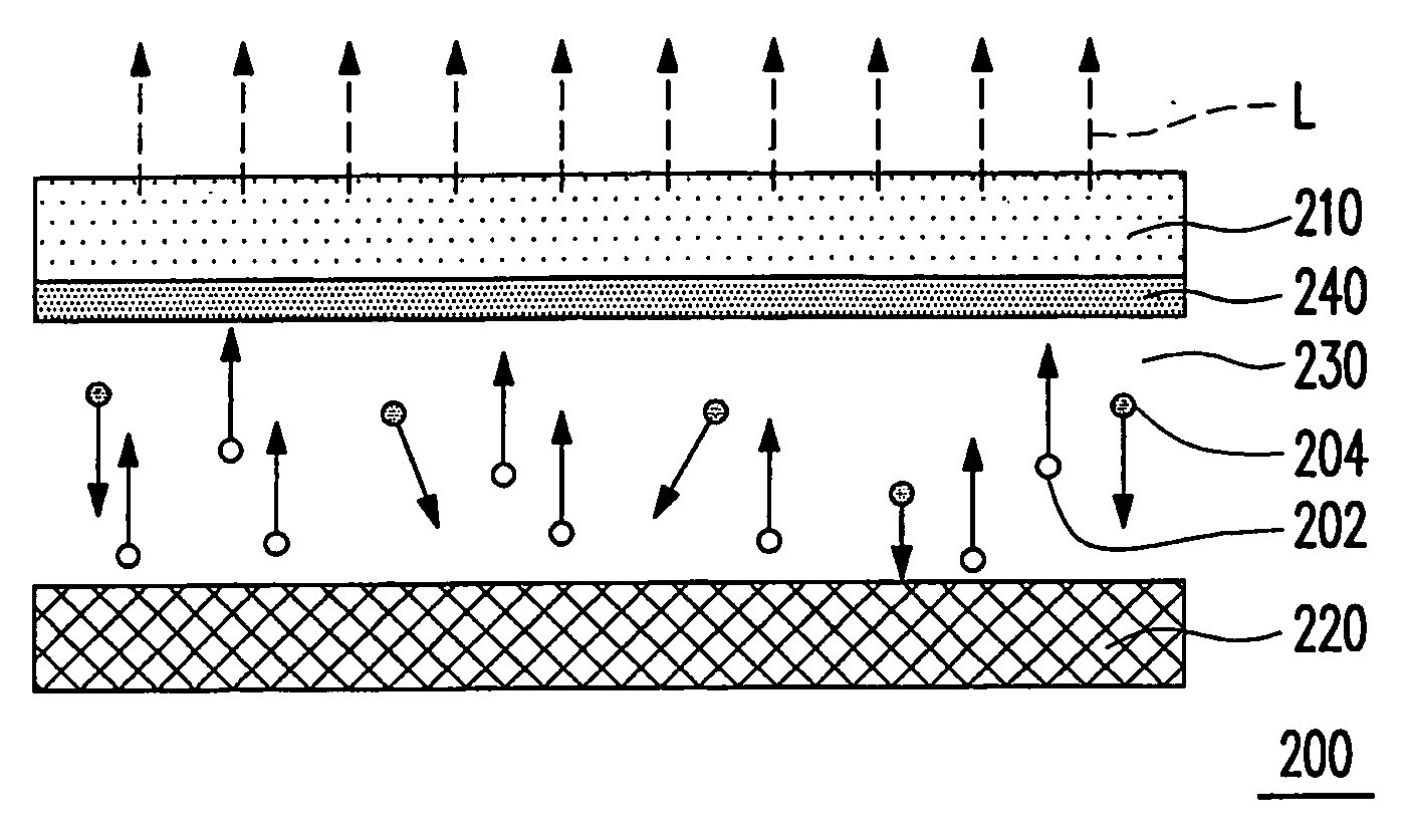
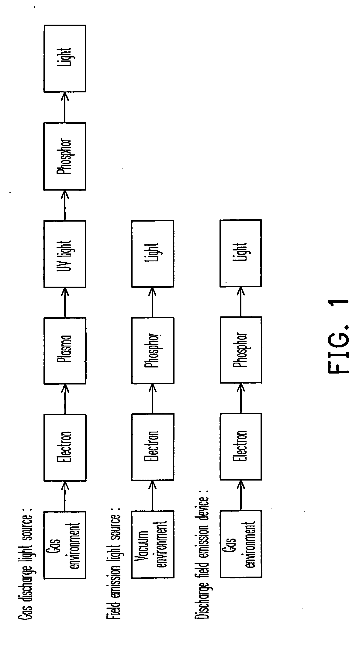
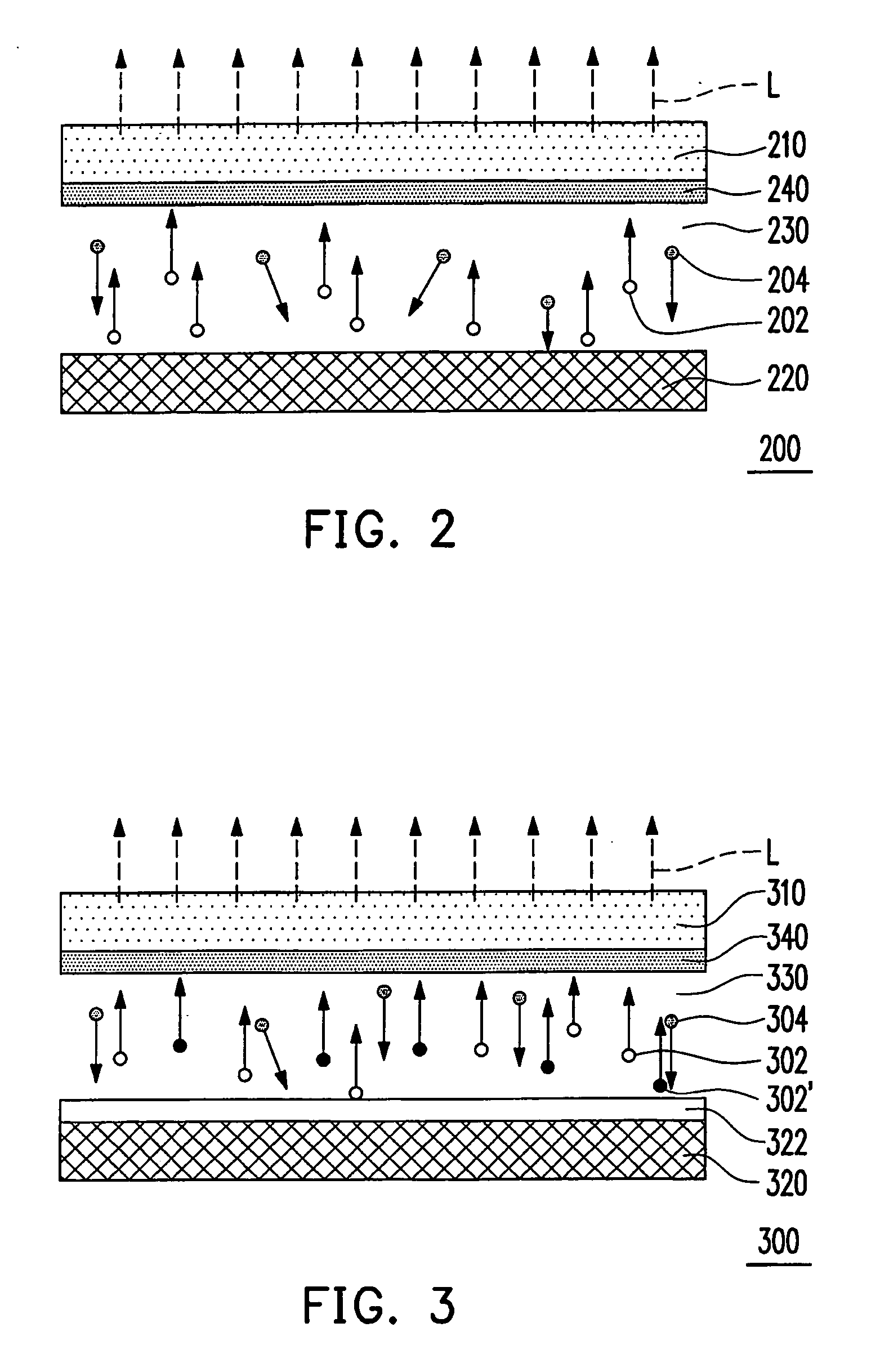
[0027]The electron emission light-emitting device provided by the present invention has the advantages of the conventional gas-discharge light source and field emission light source, and overcomes the disadvantages of the above two conventional light-emitting structures. Referring to FIG. 1, a schematic view illustrating a comparison between light-emitting mechanisms of two conventional light-emitting structures and the electron emission light-emitting device of the present invention is shown. In detail, the conventional gas glow discharge light source utilizes an electric field between the cathode and the anode to ionize the gas filled in a discharge chamber, such that the electrons impinge other gas molecule...


PUM


Abstract

An electron emission light-emitting device includes a cathode structure, an anode structure, a fluorescent layer, and a low-pressure gas layer. The fluorescent layer is located between the cathode structure and the anode structure. The low-pressure gas layer is filled between the cathode structure and the anode structure, having a function of inducing the cathode to emit electron uniformly. The low-pressure gas layer has an electron mean free path, allowing at least sufficient amount of electrons to directly impinge the fluorescent layer under an operation voltage.

Description

CROSS-REFERENCE TO RELATED APPLICATION[0001]This application is a continuation-in-part of a prior U.S. application Ser. No. 11 / 674,159, filed on Feb. 13, 2007, and also claims the priority benefit of Taiwan application serial no. 96128992, filed on Aug. 7, 2007. The U.S. application Ser. No. 11 / 674,159 claims the priority benefit of Taiwan application serial no. 95147427, filed on Dec. 18, 2006. The entirety of each of the above-mentioned patent applications is incorporated herein by reference and made a part of this specification.BACKGROUND OF THE INVENTION[0002]1. Field of the Invention[0003]The present invention generally relates to a light-emitting device, in particular, to an electron emission light emitting method and device, and applications thereof.[0004]2. Description of Related Art[0005]Currently, mass-produced light source apparatus or display apparatus mainly employ two types of light-emitting structures, which are described as follows.[0006]1. Gas-discharge light source...

Claims


Application Information

Patent Timeline
IPC IPC(8): H01J61/04
CPCH01J63/08H01J61/62
Inventor LI, JUNG-YUCHEN, SHIH-PULIN, YI-PINGLIN, WEI-CHIHCHO, LIAN-YI
Owner IND TECH RES INST
Why Eureka
Try Eureka