
Apparatus and method comprising deformable lens element

a lens element and apparatus technology, applied in the field of lenses, can solve the problems of unreliable and unpredictable system in which the lens element is employed, the bulky and energy-hungry traditional solid lens elements and motor-equipped systems, and the problem of affecting the reliability of the system,

Active Publication Date: 2008-06-19
HAND HELD PRODS
View PDF87 Cites 181 Cited by
  • Summary
  • Abstract
  • Description
  • Claims
  • Application Information

AI Technical Summary

Benefits of technology

[0036]FIG. 28 is a front perspective view of a hand held mobile terminal having a hand hel

Problems solved by technology

Fluid lens element technology has attracted the attention of many designers of optical systems who generally see traditional solid lens elements and motor equipped systems as bulky and energy hungry.
Problems have been noted with both the electro wetting and fluid injection methods for varying an optical property of a fluid lens element.
Regarding electro wetting, one problem that has been noted is that the electrical current repeatedly flowing through the lens element tends to alter the characteristics of the lens element over time, rendering any system in which the lens element is employed unreliable and unpredictable.
Another problem noted with proposals involving electro wetting is that electro wetting normally involves providing two types of fluids.
Regarding the fluid injection methods, the pumps for providing such fluid injection are necessarily complex and intricate making a reasonably costly system and acceptable miniaturization difficult to achieve.
Yet, the miniaturization and energy conservation achievable with motor-actuated rigid element equipped optical systems continues to be limited.

Method used


Image

  • Apparatus and method comprising deformable lens element
  • Apparatus and method comprising deformable lens element
  • Apparatus and method comprising deformable lens element

Examples


example 1

[0090]A focus apparatus for use in focusing having a structure substantially according to that shown in FIG. 6 is constructed and fitted onto a lens triplet imaging lens assembly of an IT5000 Image Engine of the type available from Hand Held Products, Inc. having a focal length of 5.88 mm, an F# of 6.6 and a nominal fixed best focus distance of 36 inches. An actuator from ARTIFICIAL MUSCLE INCORPORATED (“AMI”) based on the design of an MLP-95 or MSP-95 auto-focus muscle actuator available from AMI, Inc. was used. After the focus element was constructed, various voltages were applied to the actuator's flexible electrodes. The results are summarized in Table C below:

TABLE CDISTANCEMOVEMENT OFACTUATOR (20)VOLTAGEAND PRESSUREBEST FOCUS(volts)ELEMENT (4)DISTANCE0036″ 6000.025mm8″7900.050mm6″8960.075mm3″

[0091]It was observed that large variations in the best focus distance could be realized with infinitesimal movement of an actuator applying a force to a deformable lens element.

[0092][End...


PUM


Abstract

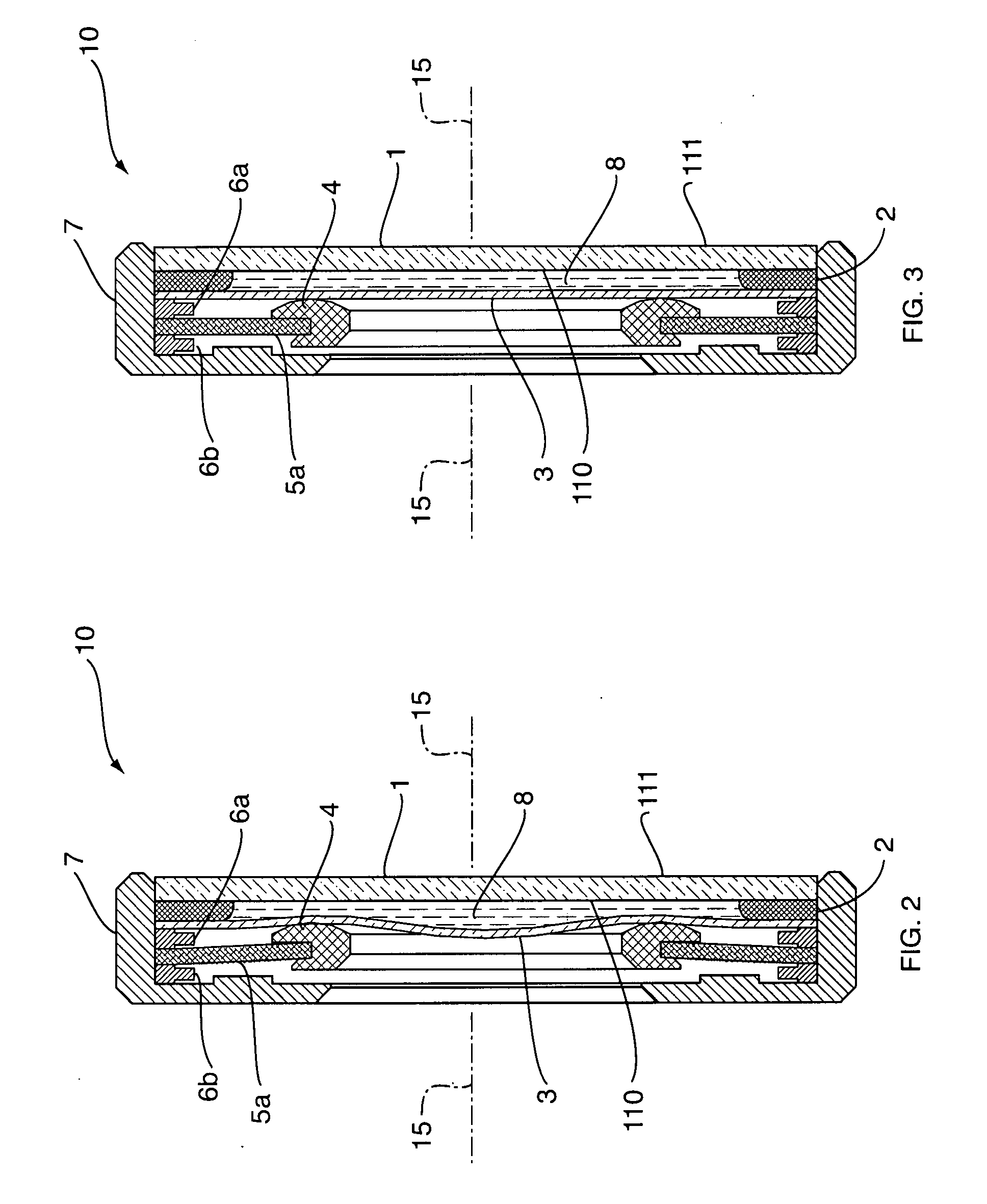
An apparatus comprising a deformable lens element can be provided wherein a deformable lens element can be deformed to change an optical property thereof by the impartation of a force to the deformable lens element.

Description

CROSS REFERENCE TO RELATED APPLICATIONS[0001]This application claims priority under 35 U.S.C. §119(e) to Provisional Patent Application No. 60 / 875,245, entitled “Focus Module and Components With Actuator Polymer Control,” filed Dec. 15, 2006 and to Provisional Patent Application No. 60 / 961,036 entitled “Variable Lens Elements And Modules,” filed Jul. 18, 2007. The above provisional patent applications are incorporated herein by reference.FIELD OF THE INVENTION[0002]The invention relates to a lens element for incorporation into an optical imaging system and specifically to an apparatus and method comprising a deformable lens element.BACKGROUND OF THE INVENTION[0003]Variable lenses, e.g., multiple focus lenses and zoom lenses have traditionally employed one or more non-deformable (i.e., rigid such as glass or polycarbonate) lens elements which are moved along an imaging axis by forces often supplied by a motor.[0004]In recent years, motorless electro-responsive lens elements have attr...

Claims


Application Information

Patent Timeline
IPC IPC(8): G02B3/10G02B3/14G06K7/10
CPCG02B7/36G02B3/14H04N23/73G02B3/0081
Inventor WANG, YNJIUN P.FENG, CHENHAVENS, WILLIAM H.LI, JIANHUA
Owner HAND HELD PRODS
Features
  • Generate Ideas
  • Intellectual Property
  • Life Sciences
  • Materials
  • Tech Scout
  • Unparalleled Data Quality
  • Higher Quality Content
  • 60% Fewer Hallucinations
Learn More