Air-Fuel Ratio Control System of Internal Combustion Engine

a technology of air-fuel ratio and control system, which is applied in the direction of electrical control, process and machine control, instruments, etc., can solve the problem that the three-way catalyst atmosphere will easily end up greatly deviating from the purification window

Active Publication Date: 2008-06-19
TOYOTA JIDOSHA KK
View PDF11 Cites 25 Cited by
  • Summary
  • Abstract
  • Description
  • Claims
  • Application Information

AI Technical Summary

Benefits of technology

[0036]That is, in the aspect of the invention of claim 14, when the rich control state judging means judges that the state is a rich control state at the time of restoration from a fuel feed cut, correction by multiplication with the first correction coefficient set depending on the intake air amount is prohibited for a predetermined period. Due to this, it is possible to reliably make the exhaust purification catalyst atmosphere a rich air-fuel ratio and possible to quickly restore the purifying action of the exhaust purification catalyst, which had dropped due to the fuel feed cut, to a suitable state.
[0037]According to the description of the claims, in an air-fuel ratio control system where the oxygen storage amount of an exhaust purification catalyst having an oxygen storage capacity is controlled to a constant level by feedback control of the target air-fuel ratio of the exhaust flowing into the exhaust purification catalyst based on the detection information of the O2 sensor and the air-fuel ratio of the exhaust flowing into the exhaust purification catalyst is controlled to that target air-fuel ratio by feedback control of the fuel injection amount based on output information of a linear air-fuel ratio sensor, there are the common effects that it is possible to make the amount of correction per unit time of the oxygen storage amount of an exhaust purification catalyst having an oxygen storage capacity constant even if the intake air amount changes, possible to prevent the exhaust purification catalyst atmosphere from greatly deviating from the purification window, and possible to improve the emission state.

Problems solved by technology

In the above way, in an air-fuel ratio control system where the oxygen storage amount of a three-way catalyst is controlled to a constant level by feedback control of the target air-fuel ratio of the exhaust flowing into the three-way catalyst based on the detection information of the O2 sensor and the air-fuel ratio of the exhaust flowing into the three-way catalyst is controlled to that target air-fuel ratio by feedback control of the fuel injection amount based on output information of a linear air-fuel ratio sensor, there is the problem that in an accelerating state or other large intake air amount state (hereinafter referred to as a “high Ga state”), there is a large correction amount of the oxygen storage amount of the three-way catalyst and the three-way catalyst atmosphere easily ends up greatly deviating from the air-fuel ratio range near the stoichiometric air-fuel ratio where the three-way catalyst removes all of the three HC, CO, and NOx components by 80% or more (hereinafter referred to as the“purification window”).
Therefore, even if the target air-fuel ratio of the exhaust flowing into the three-way catalyst is made the same target air-fuel ratio value, the larger the intake air amount, the greater the oxygen storage amount per unit time with respect to the three-way catalyst will be, that is, a phenomenon will occur that there will be a large correction amount of the oxygen storage amount of the three-way catalyst and the three-way catalyst atmosphere will easily end up greatly deviating from the purification window.

Method used


Image

  • Air-Fuel Ratio Control System of Internal Combustion Engine
  • Air-Fuel Ratio Control System of Internal Combustion Engine
  • Air-Fuel Ratio Control System of Internal Combustion Engine

Examples


first embodiment

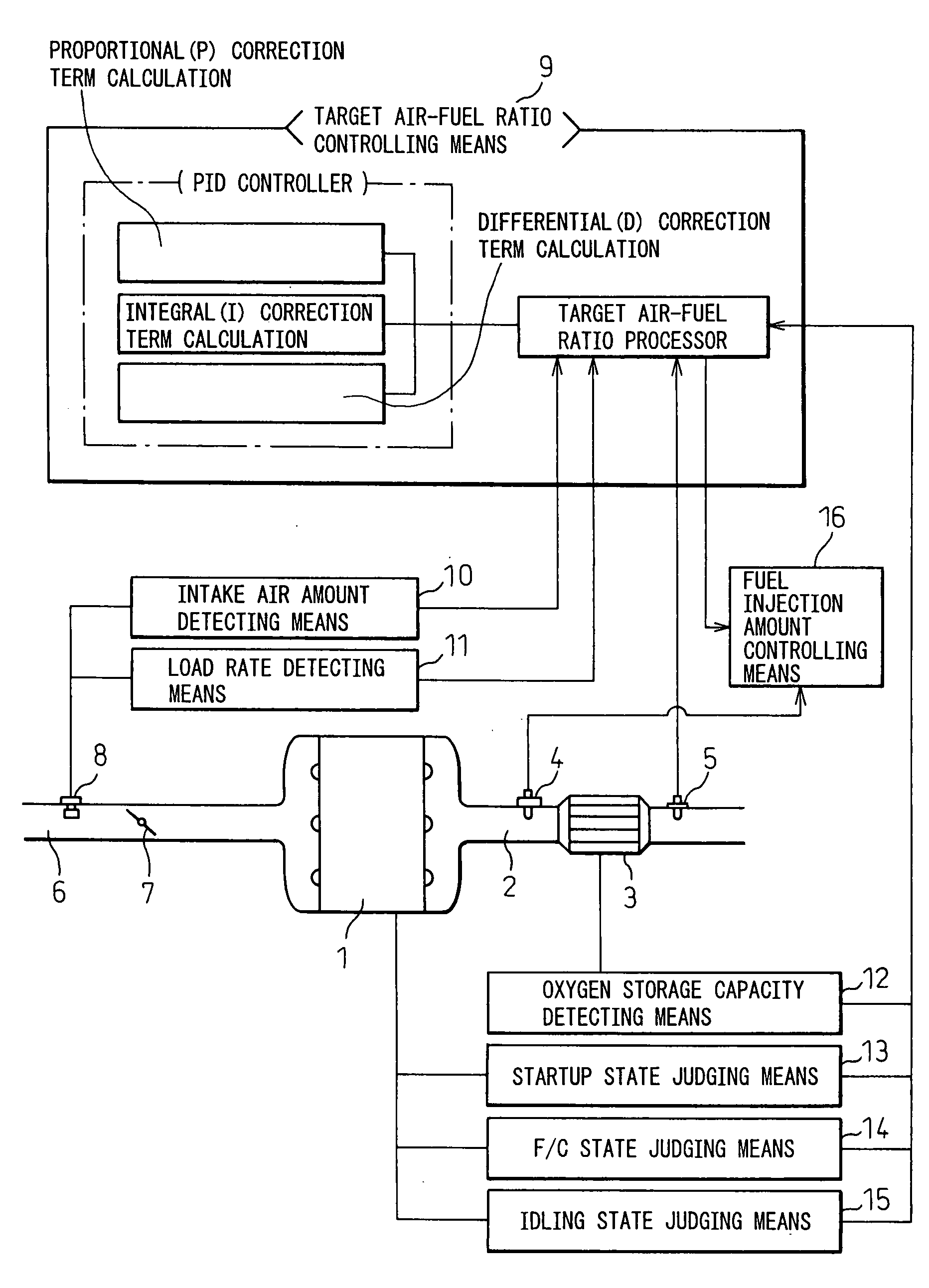
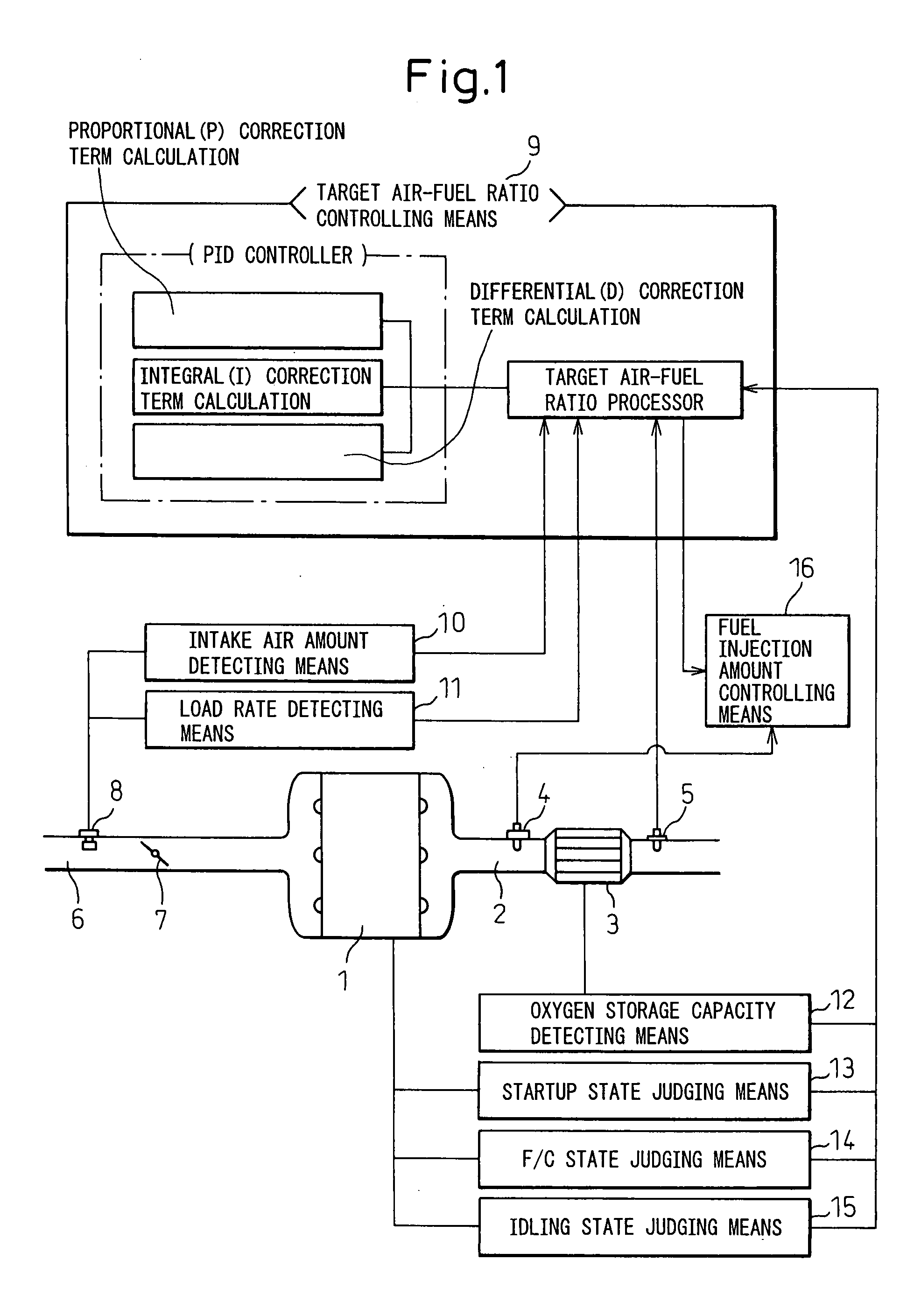
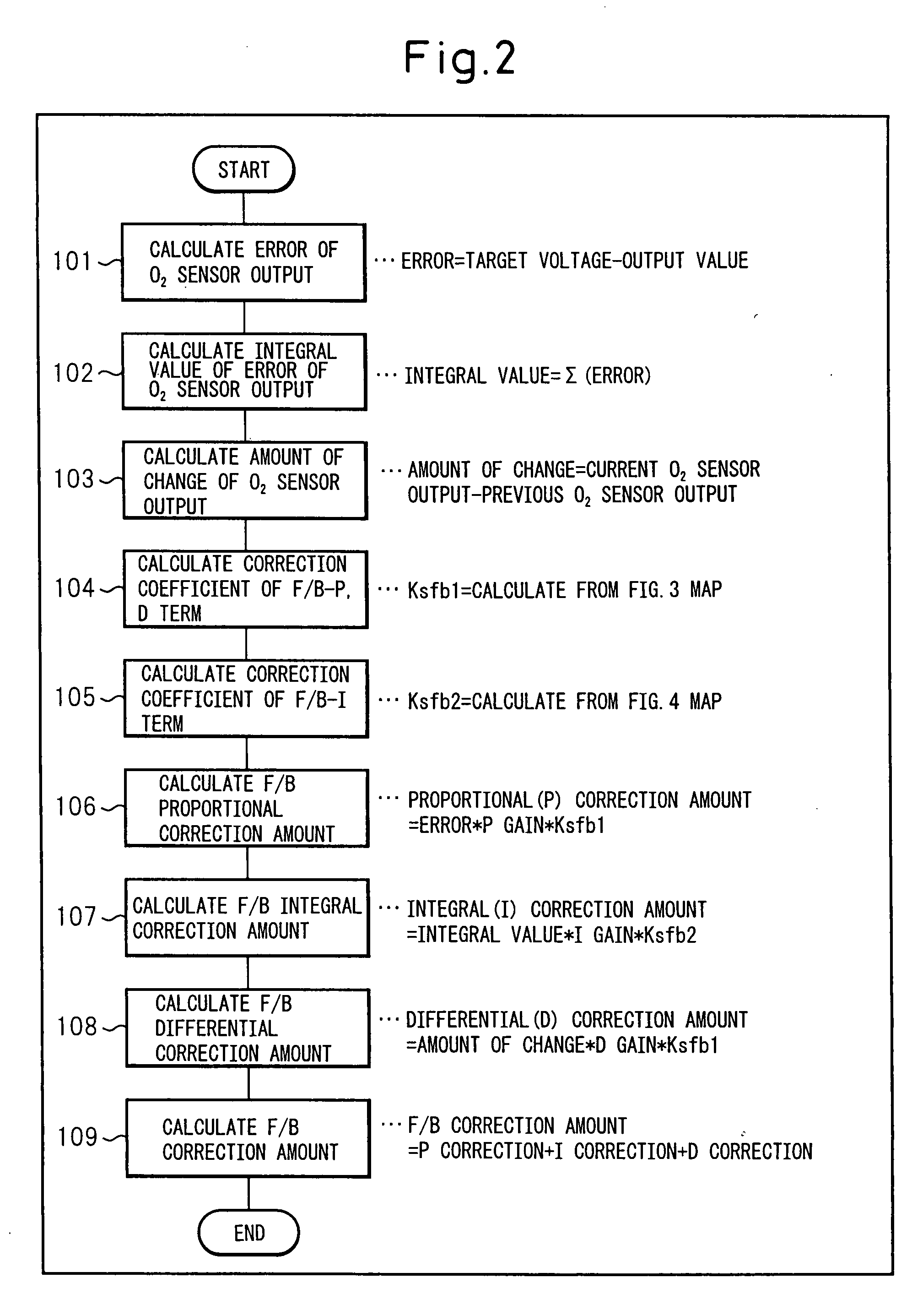
[0072]FIG. 2 is a flow chart showing a control routine of PID control calculating a correction amount of feedback control of a target air-fuel ratio of exhaust flowing into a three-way catalyst 3 as executed in the internal combustion engine shown in FIG. 1 to which the present air-fuel ratio control system is applied.

[0073]In the control routine shown in FIG. 2, first, based on the output information of the O2 sensor 5, the target air-fuel ratio processor calculates the O2 sensor output error, the integral value calculated by integrating that output error, and the amount of change of the O2 sensor output. Next, so as to make the correction amount per unit time of the oxygen storage amount of the three-way catalyst 3 constant even if the intake air amount changes, that is, so as to optimally control the amount of oxygen stored in the three-way catalyst 3 or the amount of oxygen released from the three-way catalyst 3 per unit time to be constant, the correction coefficients to be mul...

second embodiment

[0085]FIG. 5 is a flow chart showing a control routine of PID control calculating a correction amount of feedback control of a target air-fuel ratio of exhaust flowing into a three-way catalyst 3 as executed in the internal combustion engine shown in FIG. 1 to which the present air-fuel ratio control system is applied.

[0086]It is known that the maximum amount of oxygen which a three-way catalyst 3 can store, that is, the maximum oxygen storage amount, may deteriorate due to heat degradation of the three-way catalyst 3. Therefore, even if the target air-fuel ratio of the exhaust flowing into the three-way catalyst 3 is made the same target air-fuel ratio value and the intake air amount is the same, the greater the deterioration of the maximum oxygen storage amount of the three-way catalyst 3, the faster the allowable range of storage of oxygen in the three-way catalyst 3 will end up being reached and therefore the greater the possibility of the three-way catalyst atmosphere ending up...

third embodiment

[0113]Based on this, in the control routine of the third embodiment shown in FIG. 12, considering the effect of the engine speed in calculation of the correction amount of the integral correction term when processing for calculation of the correction amount of the integral correction term in feedback control of a target air-fuel ratio is executed by a processing routine synchronized with each fuel injection, a fourth correction coefficient set smaller the larger the engine speed is added as a parameter when calculating the integral correction amount in feedback control of the target air-fuel ratio. Due to this, it is possible to suppress the effect of the engine speed on control for making the correction amount per unit time of the oxygen storage amount of an exhaust purification catalyst having an oxygen storage capacity constant and possible to prevent deterioration of the exhaust emission.

[0114]Below, details of the steps will be explained.

[0115]First, at step 701, a target air-f...


PUM


Abstract

An air-fuel ratio control system maintaining constant an oxygen storage amount or oxygen release amount per unit time with respect to an exhaust purification catalyst having an oxygen storage capacity even if the intake air amount changes is provided.
An air-fuel ratio control system of an internal combustion engine having an intake air amount detecting means, a linear air-fuel ratio sensor arranged at an upstream side of an exhaust purification catalyst, an O2 sensor arranged at a downstream side of said exhaust purification catalyst, a target air-fuel ratio controlling means for performing feedback control of a target air-fuel ratio of exhaust flowing into the exhaust purification catalyst based on output information from the intake air amount detecting means and the O2 sensor, and a fuel injection amount controlling means for performing feedback control of the fuel injection amount based on output information of the linear air-fuel ratio sensor so as to achieve the target air-fuel ratio, characterized in that the target air-fuel ratio controlling means performs feedback control of the target air-fuel ratio so that even when the intake air amount changes, a correction amount per unit time of an oxygen storage amount of the exhaust purification catalyst is made constant.

Description

TECHNICAL FIELD[0001]The present invention relates to an air-fuel ratio control system of an internal combustion engine having an exhaust purification catalyst in an exhaust passage, more particularly relates to an air-fuel ratio control system of an internal combustion engine using an output value of an air-fuel ratio sensor to control a fuel feed amount and control an air-fuel ratio of exhaust flowing into the exhaust purification catalyst to a desired air-fuel ratio.BACKGROUND ART[0002]In the past, as a means for purifying exhaust gas in automotive internal combustion engines, a three-way catalyst simultaneously promoting oxidation of incompletely burned components, that is, HC (hydrocarbons) and CO (carbon monoxide), and reduction of the NOx (nitrogen oxides) formed by reaction of the nitrogen in the air and the oxygen remaining unburned has been utilized. To raise the oxidation and reduction abilities of such a three-way catalyst, it is necessary to control the air-fuel ratio, ...

Claims


Application Information

Patent Timeline
Patent Type & Authority Applications(United States)
IPC IPC(8): F02D41/00F02D41/06F02D45/00F01N3/18F01N3/24F02D41/12F02D41/14
CPCF02D41/1441F02D41/1454F02D41/1456F02D2200/0814F02D2041/1422F01N2560/025F01N2560/14F02D2041/1409F02D41/123F01N3/24F02D41/08F02D41/14F02D45/00
Inventor NAKAGAWA, NORIHISAFUJIWARA, TAKAHIKOHAGIMOTO, TAIGAKAKO, JUNICHIKATO, NAOTOOKAZAKI, SHUNTARO
Owner TOYOTA JIDOSHA KK
Why Eureka
Try Eureka