
Substrate storage container

a substrate and storage container technology, applied in the direction of valve operating means/releasing devices, functional valve types, transportation and packaging, etc., can solve the problems of increasing complexity, unable to effectively prevent a trace amount of organic matter in the clean room, and purging gas charged through the filter, etc., to achieve the effect of preventing displacement of the valve, reducing the complexity of the operation, and simplifying the structure of the valve attachmen

Inactive Publication Date: 2008-06-26
SHIN-ETSU POLYMER CO LTD
View PDF12 Cites 3 Cited by
  • Summary
  • Abstract
  • Description
  • Claims
  • Application Information

AI Technical Summary

Benefits of technology

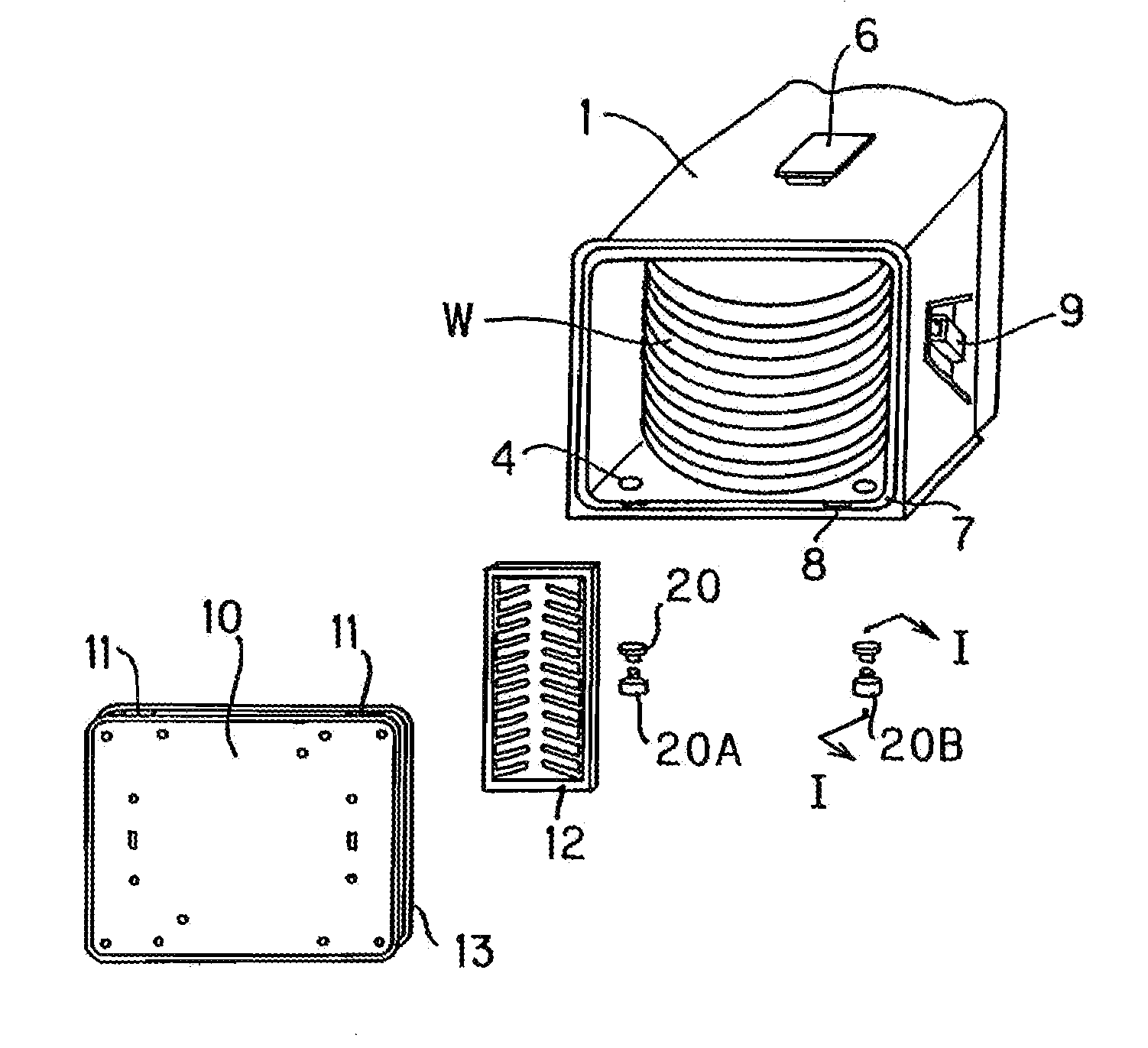
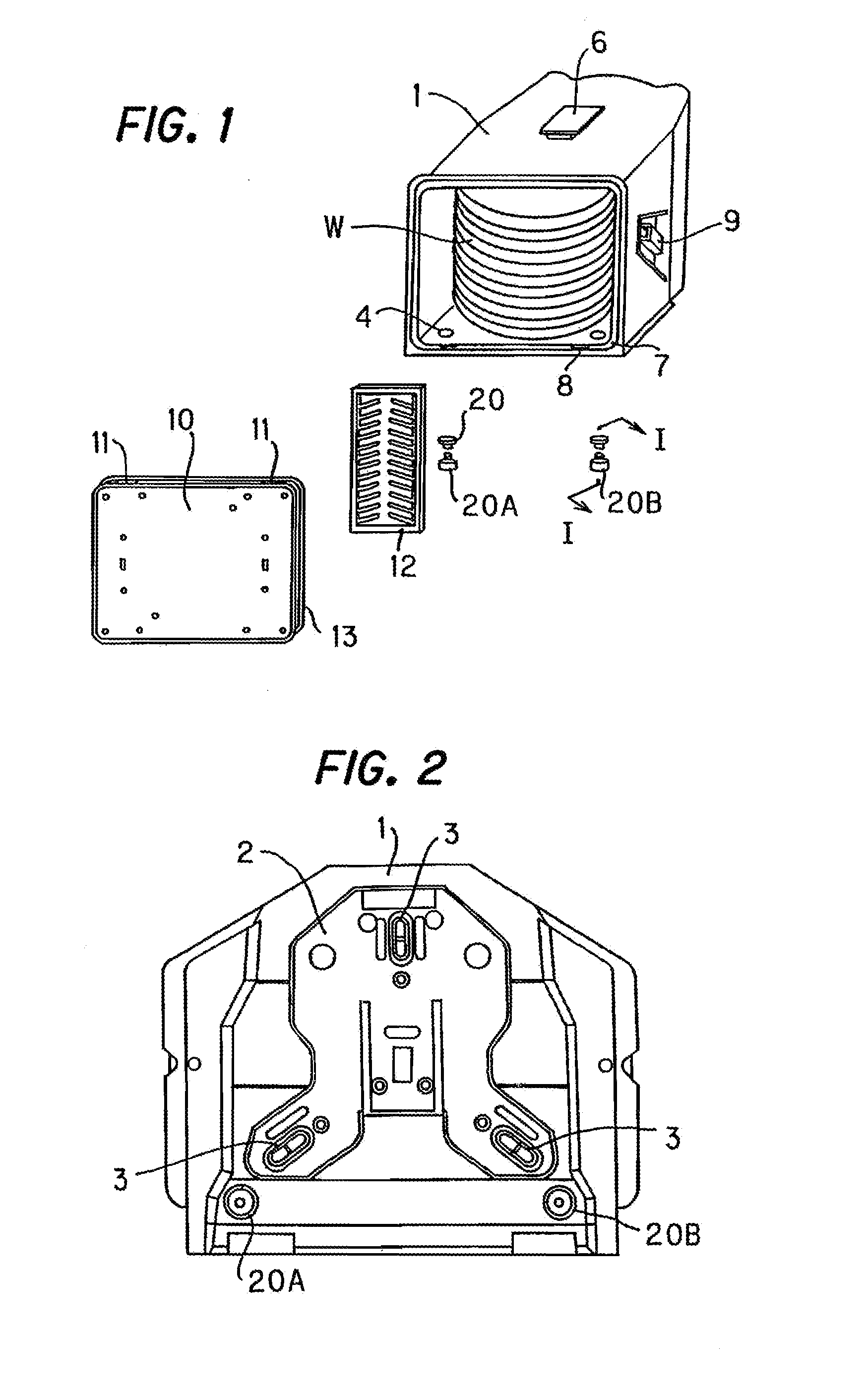
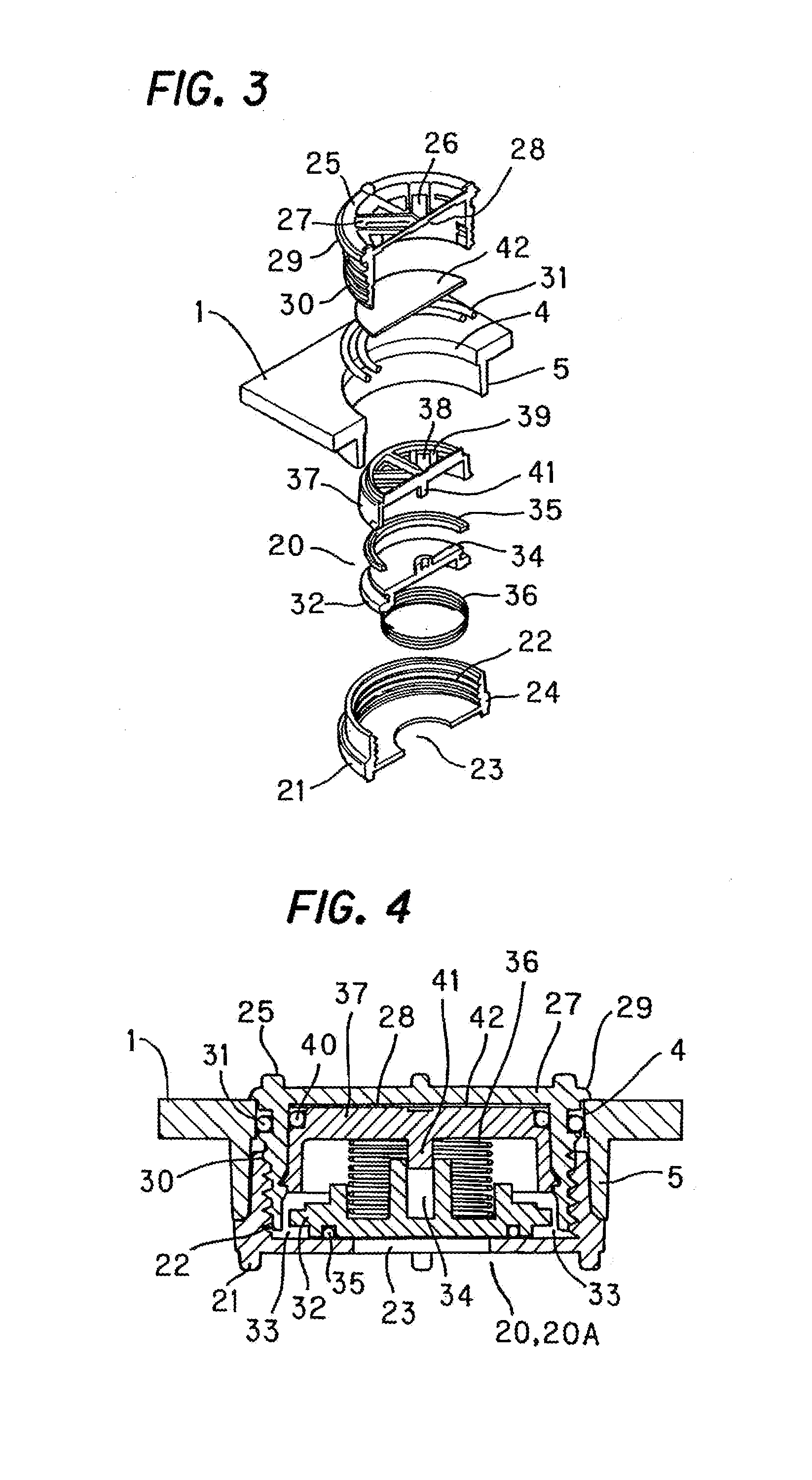
The present invention provides a substrate storage container with a simplified engagement structure for valve attachment, prevention of valve displacement, and efficient prevention of contamination from purging gas. The container includes a container body, a door for opening and closing the container, and a valve unit attached to a through-hole in the container body or the door. The valve unit includes a fixed sleeve, a holding sleeve, an elastic check valve, and an interior lid sleeve. The elastic check valve is designed to prevent incomplete sealing and inflow of contaminants from the outside. The container also allows for long-term holding of purging gas and efficient prevention of contamination from purging gas.

Problems solved by technology

First, in the case where gas purge is performed with a valve attached to the substrate storage container, an engagement structure for valve attachment is needed. However, this engagement structure increases the complexity of the arrangement. An ordinary valve has a hollow portion with a narrow opening, and a shutoff valve that closes this opening is provided to come into contact with a tapered portion of the opening, creating a sealing structure. This shutoff valve is readily displaced by repeated usage, resultantly presenting a leakage problem due to imperfect seal. Further, since the ordinary valve incorporates more than a few metallic parts such as a spring for valve control and the like, there is a fear that a very small quantity of metal ions, discharged from the metal parts while the substrate storage container is put in storage or during its cleaning, infiltrates into the substrate storage container, contaminating semiconductor wafers.
In this case, however, there is a problem in that the purging gas charged through the filter, however, cannot be kept inside the substrate storage container.
There is also a problem in that it is impossible to effectively prevent a trace amount of organic matter in the clean room from flowing into the interior of the substrate storage container from exterior because there is a passage between inside and outside of the substrate storage container.

Method used


Image

  • Substrate storage container
  • Substrate storage container
  • Substrate storage container

Examples


second embodiment

[0082]Next, FIGS. 10 and 11 show the present invention. In this case, a check valve 32A is constructed so as to be used both in a gas inlet valve 20A and in a gas discharge valve 20B.

[0083]Check valve 32A basically is a solid form having an approximately convex-top section, with a pair of round holes for guided parts 34, formed at the center thereof in both the front and rear sides. An annular sealing element 35 is fitted along the periphery of the underside. The check valve is formed marginally smaller than the inside diameter of an interior lid sleeve 37. A pair of guided parts 34, not being connected to each other, have a partition therebetween. When the valve is used as a gas inlet valve 20A, this check valve 32A is set with its projected portion up, as shown in FIG. 10. When the valve is used as a gas discharge valve 20B, the check valve is set upside down as shown in FIG. 11.

[0084]Interior lid sleeve 37 basically has a configuration similar to that of the above embodiment, how...

third embodiment

[0087]Next, FIGS. 12 to 18 show the present invention. In this case, each valve unit 20 is constructed of a fixed sleeve 21 that is removably attached to rib 5 of a through-hole 4 of a container body 1 from below and forms the gas flow passage, a holding sleeve 25, removably attached to through-hole 4 of container body 1 from above with an O-ring 31 for sealing interposed therebetween and screw fitted with fixed sleeve 21, an elastic check valve 32B built in for defining a clearance 33 between the fixed sleeve 21 and the holding sleeve 25, an elastically deformable element 36A having air permeability and continuous porosity, deforming the check valve 32B, an interior lid sleeve 37 that is in contact with elastically deformable element 36A and forms the gas flow passage and a disk-shaped filter 42 interposed between holding sleeve 25 and interior lid sleeve 37 while no guided part 34 and guide element 41 is provided. Each valve unit 20 is used for plural gas inlet valves 20A and gas ...

fourth embodiment

[0098]Next, FIG. 19 shows the present invention. In this case, a nozzle tower 43 that is connected to a valve unit 20 is made to stand at some or all of through-holes 4 in a container body 1.

[0099]Nozzle tower 43 is basically a hollow cylinder, formed of a predetermined resin such as, for example, polycarbonate, polyetherimide, polyetheretherketone, cycloolefin polymer or the like, and has a row of holes arranged vertically at intervals of a predetermined distance as gas ejection ports 44, on the peripheral wall thereof opposing the side of semiconductor wafers W, whereby gas is fed from these ejection ports 44 toward the semiconductor wafers W. Sectional size of these ejection ports 44 may be all equal in size or may be formed to be gradually greater from the bottom to the top. Other components are the same as that of the above embodiment so the description is omitted.

[0100]Also in this embodiment, the same operation and effect as that in the above embodiment can be expected. Besid...


PUM


Abstract

A substrate storage container includes a container body for accomodating and aligning semiconductor wafers, a door which opens and closes the front of the container body and a pair of valve units disposed at the bottom of the container body for controlling gas flow. Each valve unit includes a fixed sleeve for gas flow, fitted in a rib of a through-hole of the container body, a holding sleeve fitted in the through-hole of the container body with an o-ring interposed therebetween and mated and threaded with the fixed sleeve, a check valve built between the fixed sleeve and the holding sleeve, leaving a clearance, an elastically deformable element for opening and closing the check valve, an interior lid sleeve for gas flow, opposing the check valve and supporting the elastically deformable element, and a filter interposed between the holding sleeve and the interior lid sleeve.

Description

TECHNICAL FIELD[0001]The present invention relates to a gas-purgeable, substrate storage container for storing substrates such as semiconductor wafers, photomask glass, and detailedly relates to a valve unit for gas purging, for controlling the gas flow, both into and from, the substrate storage container.BACKGROUND ART[0002]In the recent semiconductor industry, as seen in the case of DRAM (Dynamic Random Access Memory) production, while there has been competition for acquisition of market-share due to cost reduction of semiconductor devices, revision of the production system, for cost reduction, as well as development of semiconductor wafers used for production of semiconductor devices into large sizes (300 mm or greater) have been in progress.[0003]As to the revision of the production system, there is an example where the system in which the whole semiconductor manufacturing plant is kept as a highly clean environment (e.g. class 10 clean or above) to manufacture semiconductor dev...

Claims


Application Information

Patent Timeline
Patent Type & Authority Applications(United States)
IPC IPC(8): B65D85/00F16K15/02H01L21/00H01L21/673
CPCF16K15/026H01L21/67393H01L21/67379H01L21/67017Y10T137/7834F16K17/04H01L21/68B65D85/48F16K15/063
Inventor SUMI, ATSUSHITODA, JUNYANAKAYAMA, TAKAYUKI
Owner SHIN-ETSU POLYMER CO LTD
Learn More