Temperature control device

a technology of temperature control device and temperature control device, which is applied in the direction of electric/magnetic/electromagnetic heating, domestic stoves or ranges, lighting and heating apparatus, etc., can solve the problem of spontaneous cooling of objects to be processed

Inactive Publication Date: 2008-06-26
SEMICON ENERGY LAB CO LTD
View PDF43 Cites 64 Cited by
  • Summary
  • Abstract
  • Description
  • Claims
  • Application Information

AI Technical Summary

Benefits of technology

[0012]In addition, the temperature control device of the present invention may detect not only the temperature of the object to be processed but also the temperature of the heater.
[0013]The temperature control device of the present invention can charge a rechargeable

Problems solved by technology

However, the object to be processed is spontaneously cooled down after the dielectric heating.
Thus, in a case of heating food as an object to be processed, there has been a problem in that people have had no

Method used


Image

  • Temperature control device
  • Temperature control device
  • Temperature control device

Examples


embodiment mode 1

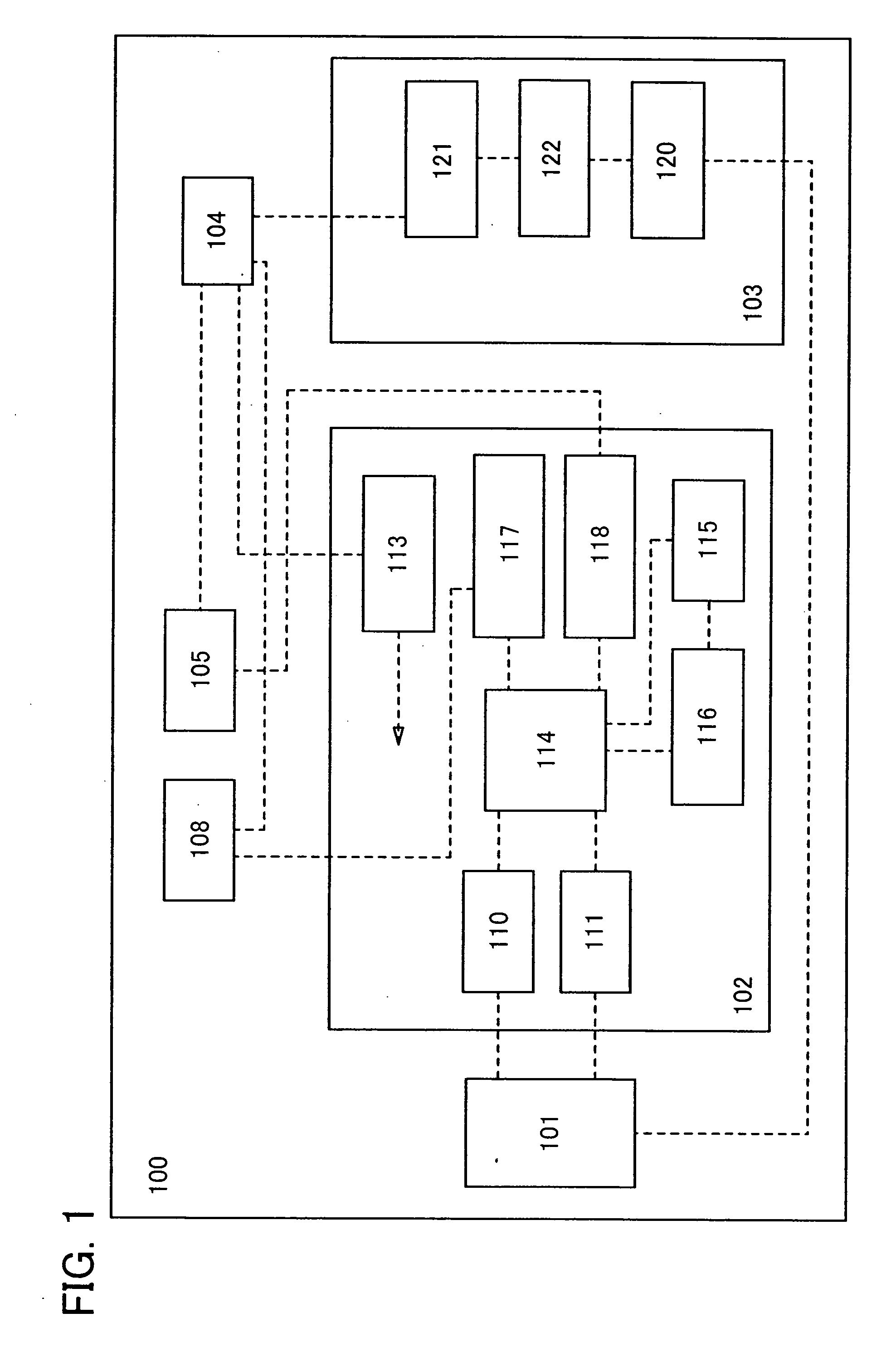
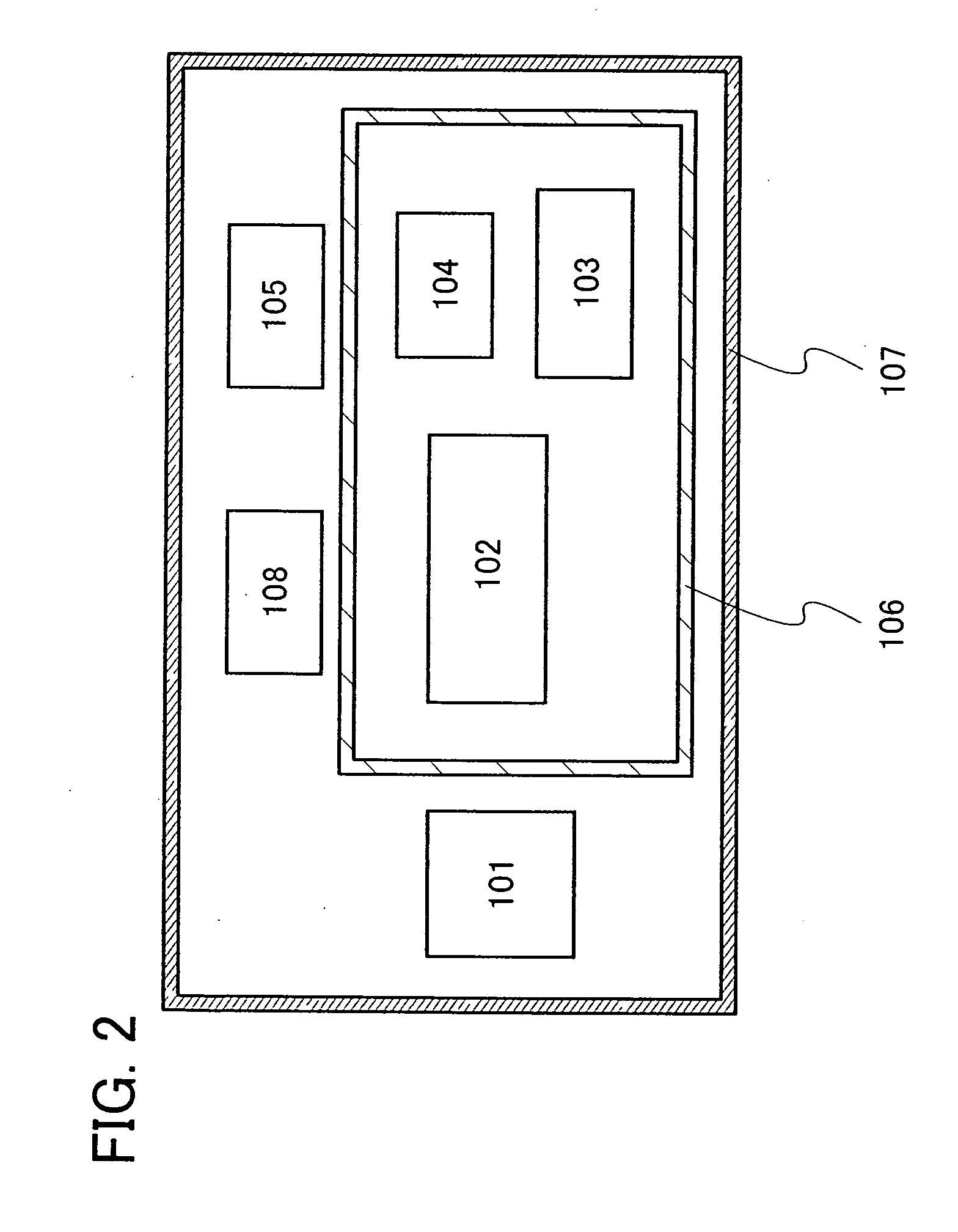
[0021]A structure of a temperature control device of the present invention will be described with reference to a block diagram of FIG. 1.

[0022]A temperature control device 100 shown in FIG. 1 includes an antenna 101, a signal processing circuit 102, a charging circuit 103, a rechargeable battery 104, a temperature sensor 108, and a heater 105. The signal processing circuit 102 includes a modulation circuit 110, a demodulation circuit 111, a first power supply circuit 113, a logic circuit 114, a memory circuit 115, a memory control circuit 116, a sensor control circuit 117, and a heater control circuit 118. The charging circuit 103 includes a rectifier circuit 120, a second power supply circuit 121, and a charge control circuit 122.

[0023]Note that the temperature control device of the present invention is acceptable as long as it can operate using AC voltage generated in the antenna 101, and the temperature control device of the present invention does not necessarily include the ante...

embodiment mode 2

[0038]Next, a specific structure of a temperature control device of the present invention will be described.

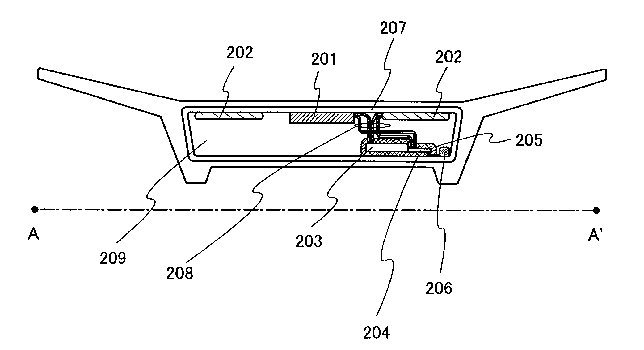
[0039]FIGS. 3A and 3B show one mode of the temperature control device of the present invention. FIG. 3A corresponds to a perspective view of a temperature control device 200 of this embodiment mode, and FIG. 3B corresponds to a top view thereof. In addition, FIG. 5 corresponds to a cross-sectional view taken along a dashed line A-A′ of FIG. 3B. The temperature control device 200 shown in FIGS. 3A and 3B has a shape capable of having an object to be processed such as food thereon or containing it therein. A temperature sensor 201 is provided so as to be in contact with or adjacent to an object to be processed. In addition, the temperature control device 200 includes a heater 202. The heater 202 is provided so as to have distance with the temperature sensor 201 and also so as to be in contact with or adjacent to an object to be processed.

[0040]A rechargeable battery 203 and a si...


PUM


Abstract

A temperature control device which can control the temperature of an object to be processed even after supply of radio waves or electromagnetic waves from a high-frequency heating apparatus is stopped. The temperature control device includes a temperature sensor detecting the temperature of the object to be processed heated by radio waves generated from the high-frequency heating apparatus, a signal processing circuit comparing the temperature detected by the temperature sensor with a standard temperature, a rechargeable battery charged by electric energy generated by reception of the radio waves by an antenna, a charging circuit controlling charging of the rechargeable battery, and a heater supplied with electric power from the rechargeable battery to heat the object to be processed so that the temperature thereof gets closer to the standard temperature, in accordance with a comparison result by the signal processing circuit.

Description

BACKGROUND OF THE INVENTION[0001]1. Field of the Invention[0002]The present invention relates to a temperature control device which can control temperature wirelessly.[0003]2. Description of the Related Art[0004]In recent years, an electric power transmission technique and an individual identification technique utilizing wireless communication using radio waves, electromagnetic waves, or the like has attracted attention. An individual identification technique has been used for a wireless tag referred to as an RFID tag, an IC tag, an IC chip, an RF tag, an electronic tag, or the like. An electric power transmission technique has been used for charging some home electronic appliances. For example, products such as an electric toothbrush and an electric shaver have been put on the market.[0005]In addition, a technique in which wireless communication and a high-frequency heating apparatus provided with a high-frequency device, such as a microwave, are combined has been considered. A hig...

Claims


Application Information

Patent Timeline
IPC IPC(8): H02J17/00H02J7/00H05B6/68A47J27/00A47J36/00F24C7/02
CPCH02J7/00H02J17/00H05B6/66H05B6/6402H05B6/645H02J50/23H02J50/27H02J7/0068H02J50/20
Inventor TAMURA, HIKARU
Owner SEMICON ENERGY LAB CO LTD
Why Eureka
Try Eureka