
Reaming tool and a process for manufacturing such reaming tool

Inactive Publication Date: 2008-06-26
UNIMERCO
View PDF0 Cites 24 Cited by
  • Summary
  • Abstract
  • Description
  • Claims
  • Application Information

AI Technical Summary

Benefits of technology

[0010]It is an object of the invention to provide a reaming tool and a process for the manufacture of such reaming tool, which ensures that the tool can be manufactured cost-effectively and satisfies the high quality requirements of such tools and of the work-piece being worked.

Problems solved by technology

The use of blanks with high hardness cutting materials provided in helical flutes and extending around the enveloping surface appears to be erroneous compared to milling tools.
Furthermore, end millers operate at relatively high cutting speeds and depths of cut, so that quite other forces act on a head of an end miller.
For the use of reaming tools, because of the forces, parameters and requirements which deviate from milling technology, the use of high hardness cutting material appear to be erroneous to form the reaming tool by means of a body, which has on its enveloping surface substantially helical flutes into which high hardness cutting material is sintered or soldered.
Cutters are provided with nicks, said nicks being provided at respective land sections, Cutting operation is shared by respective cutters, thus reducing the cutting resistance and promoting radiation of cutting heat.
It is experienced that all of the known reaming tools expose the work-piece to vibrations having a great negative influence on the quality of the reaming process.
This is especially the case, where the reaming process extends over a relatively long distance, and also where the work-piece is difficult to properly fix and / or is of a relatively light material.

Method used


Image

  • Reaming tool and a process for manufacturing such reaming tool
  • Reaming tool and a process for manufacturing such reaming tool
  • Reaming tool and a process for manufacturing such reaming tool

Examples


Embodiment Construction

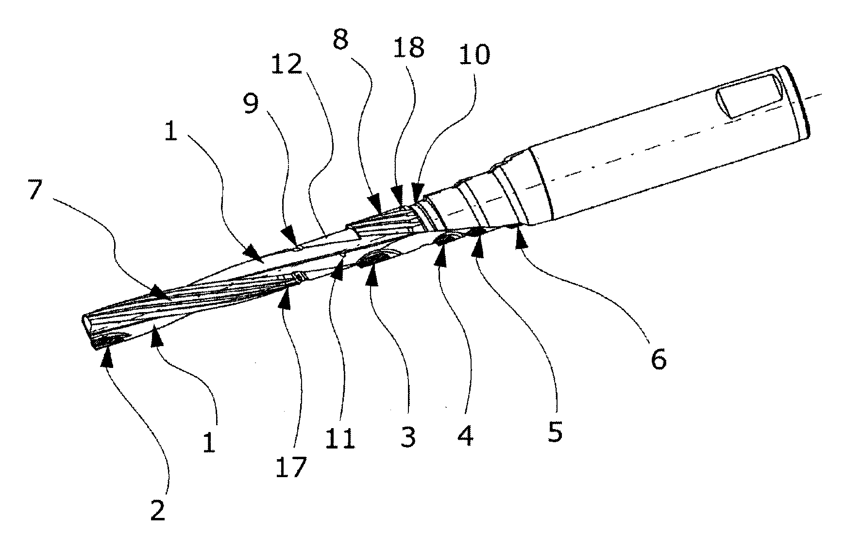
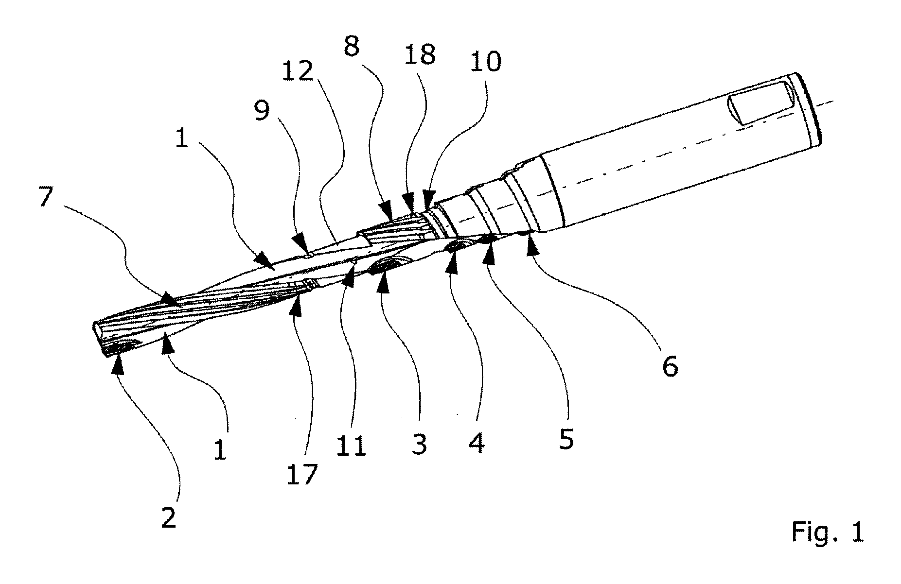
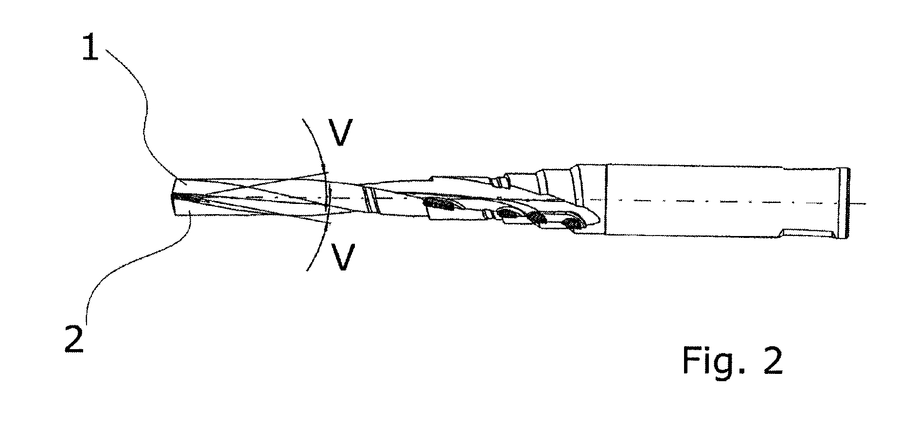
[0042]FIG. 1 shows an embodiment of a reaming tool provided with two helical flutes 1 and with high hardness cutting elements 2,3,4,5,6 provided in different reaming steps as part of the reaming tool. In the embodiment shown, the reaming tool—apart from the helical flutes 1 and the high hardness cutting elements 2,3,4,5,6—is provided with so-called guide pads 7,8, and with so-called swarf channels 9,10. The embodiment of the reaming tool is also provided with coolant holes for providing cooling liquid to the reaming process. The high hardness cutting elements are divided into a cutting element 2 in an initial reaming step and additionally high hardness cutting elements 3,4,5,6 for reaming in a work-piece (see FIG. 7A-7B) of secondary holes with larger diameters and provided in extension of a primary hole having the smallest diameter in the work-piece. Such secondary holes may be holes provided in the work-piece for insertion of bearings and / or seals for any axle or rod extending thr...


PUM

PropertyMeasurementUnit
Strengthaaaaaaaaaa
Hardnessaaaaaaaaaa
Durabilityaaaaaaaaaa

Abstract

The invention relates to a reaming tool which has on its enveloping surface substantially helical flutes. High hardness cutting materials are brazed or soldered to the base material of the reaming tool. Thus, a cost-favourable manufacture of a reaming tool is provided. The invention makes it possible for the shaft and the head of the reaming tool to be made of solid carbide metal, the shaft and the head preferably constituting the one and same integrate body. A considerable improvement is obtained as regards the processing quality, the speed, and also the durability of the tool. This is based on the fact that the chip removal elements are sintered or brazed into the base body of the head initially shaped with the helical flutes, so that a material joint of high quality is provided compared to other joints.

Description

FIELD OF THE INVENTION[0001]The invention relates to a reaming tool having on its enveloping surface substantially helical flutes, into which high hardness cutting materials are brazed or soldered. Reaming tools are used for the fine machining of bore holes and therefore require a precise arrangement and design of chip removal elements and other elements in contact with the bore hole. In particular, a high degree of dimensional accuracy is necessary. Reaming tools have already been known in which the chip removal elements are set into a base body, for example by brazing or by adhesion.BACKGROUND OF THE INVENTION[0002]It is known from milling tools to use base bodies with groove-shaped recesses extending along an enveloping surface, and into which very hard cutting materials, such as a Poly-Crystalline Diamond (PCD) material or a Cubic Boron Nitride (CBN) material, are sintered or soldered. Such blanks for milling tools may be processed by a spark erosion process in order to produce ...

Claims


Application Information

Patent Timeline
IPC IPC(8): B23D77/00B23P15/46
CPCB23D77/006B23D77/02B23D77/12B23D2277/061B23D2277/10B23D2277/2435Y10T408/81B23D2277/30B23D2277/52B23D2277/82B23P15/46Y10T408/89Y10T408/9097B23D2277/245
Inventor JENSEN, PER HOLMWIDHALM, SAMUEL T.MANN, GARY M.
Owner UNIMERCO
Learn More