Battery pack

a battery pack and core pack technology, applied in the field of batteries, can solve the problems of difficult to achieve mass production of core packs with efficiency, easy to be split between, leakage of plastic materials,

Inactive Publication Date: 2008-06-26
SANYO ELECTRIC CO LTD
View PDF8 Cites 51 Cited by
  • Summary
  • Abstract
  • Description
  • Claims
  • Application Information

AI Technical Summary

Benefits of technology

[0014]The above-described battery pack carries the advantage that the sealing groove, provided between the exposed portion and the resin molded portion, prevents the exposed portion of the connector from being covered by the plastic material for forming the resin molded portion, and further both the capillarity groove provided to the connector and the sealant filled in the groove prevent the plastic material from penetrating inside the connector. Because of this structure, in the battery pack, the exposed portion is not covered with the plastic material and also the plastic material is not introduced into the connector, so that a poor contact of the output terminal of the connector can be limited to an extremely low level.

Problems solved by technology

This state happens because when the battery core pack is temporally tacked to a metal mold to form the resin molded portion, a gap is prone to be produced between the metal mold and the connector, and the plastic material leaks through the gap to cover the exposed portion.
Because of this process, any slight gap existing between the connector and the metal mold may cause a leakage of the plastic material which is injected under a pressure.
In view of such requirements, an assembly of the battery core pack is made more difficult, and further because a high dimensional accuracy is required of the used components, it becomes difficult to achieve a mass production of the core pack with efficiency and ease, disadvantageously resulting in a higher cost of production.
Further, in the battery pack, which has the connector fixed to the circuit board and inserted into the resin molded portion, the plastic material for forming the resin molded portion is prone to leak through the gap existing between the connector and the circuit board.
Such leaked plastic material will cause a poor contact for the output terminal incorporated in the connector.
However, it is highly time-consuming to unfailingly fill the sealant such that no gap will be present between an entire circumference of the connector and the circuit board, which can be an additional factor for a higher cost of the battery core pack production, being accompanied by a lower efficiency in production.

Method used


Image

  • Battery pack
  • Battery pack
  • Battery pack

Examples


Embodiment Construction

)

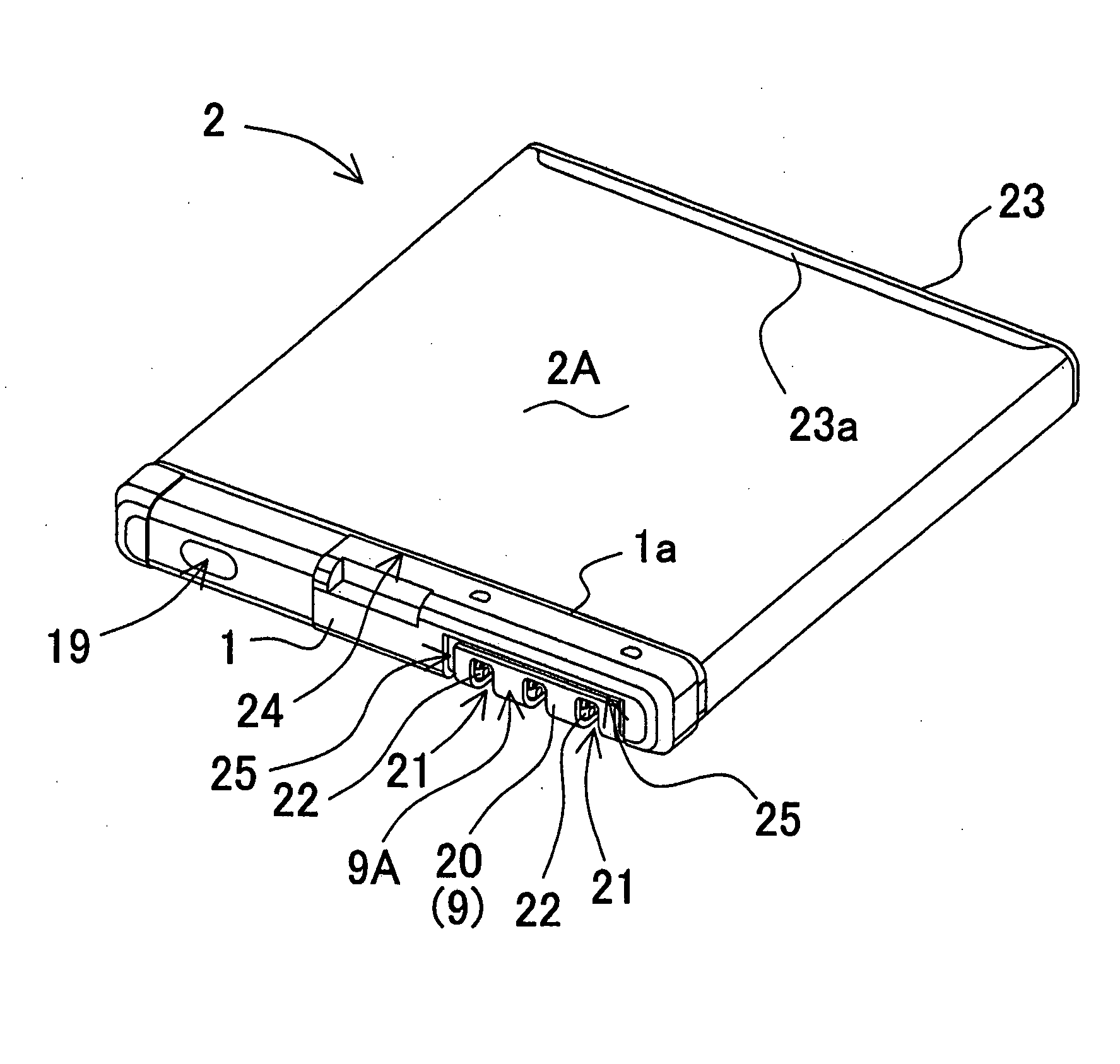
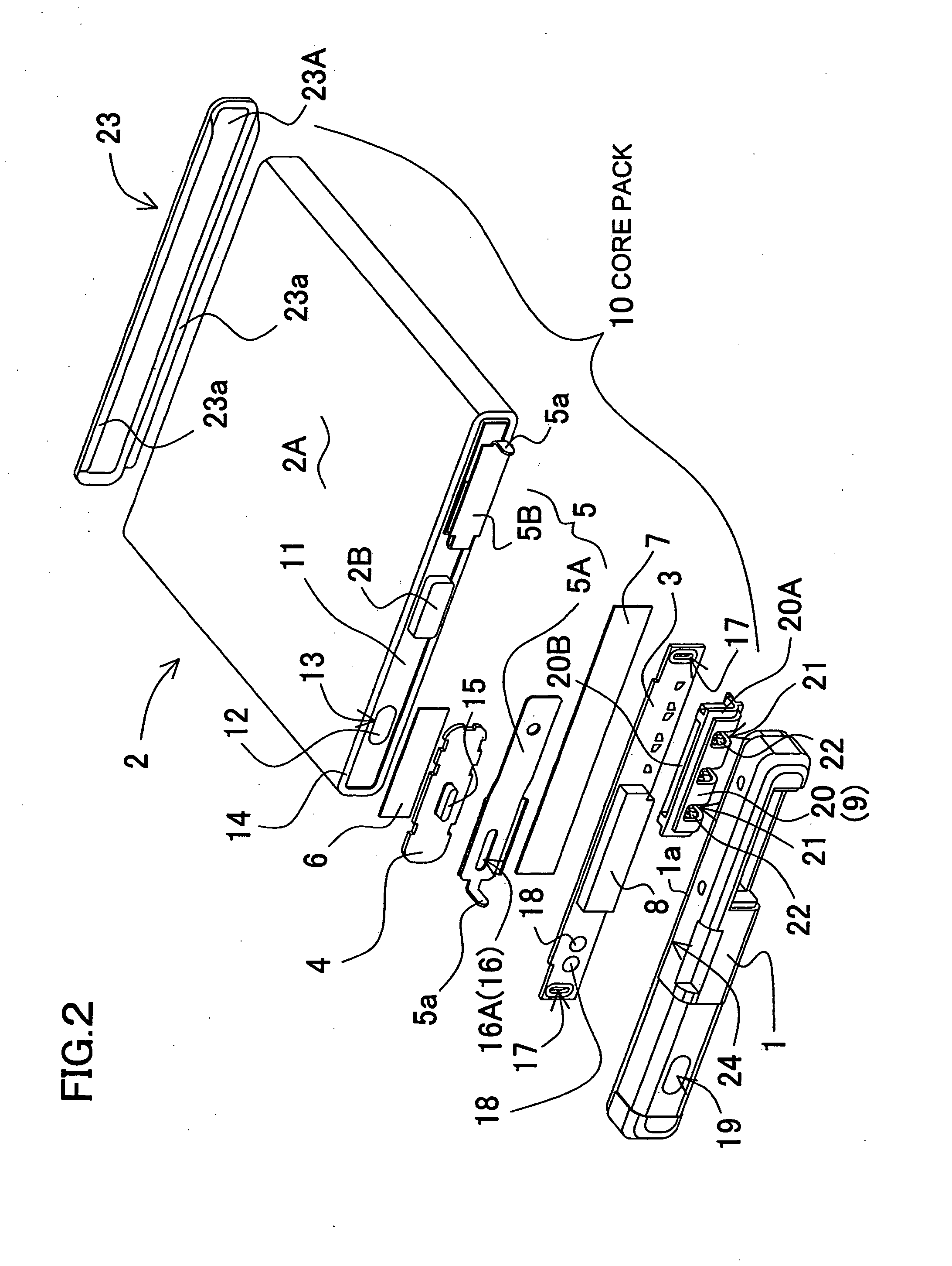
[0027]The battery pack shown in FIG. 1 through FIG. 4 is produced by insert-molding a battery core pack 10 into a resin molded portion 1. FIG. 2 is an exploded perspective view of the battery pack. In order to facilitate a better understanding of each individual component, this Figure shows a separated state of a resin molded portion 1, a circuit board 3, a connector 9, a lead plate 5, an insulation cover 4, and a unit cell 2. In the process of forming the resin molded portion 1 for the battery pack, the circuit board 3 to which the connector 9 is fixed, the lead plate 5, and the insulation cover 4 are inserted into the resin molded portion 1. Therefore, when the resin molded portion 1 has been formed of a plastic material, the battery core pack 10 comes to be integrally structured with the resin molded portion 1. In the illustrated battery pack, a part of the battery core pack 10 is insert-molded into the resin molded portion 1, but the present invention does not limit the part of...


PUM

PropertyMeasurementUnit
distanceaaaaaaaaaa
thicknessaaaaaaaaaa
thicknessaaaaaaaaaa

Abstract

In a battery pack, a battery core pack having a connector is inserted into a resin molded portion which is formed of a plastic material. The battery core pack includes a rechargeable unit cell, a circuit board electrically connected to the unit cell, and a connector fixed to the circuit board. The connector incorporates a contact point in a connector casing which is formed of an insulation material, and the connector casing is inserted into the resin molded portion so as to partially appear to a surface of the resin molded portion. Further, the battery pack is provided with a sealing groove at a boundary between the connector casing and the resin molded portion, along a peripheral edge of an exposed portion of the connector, appearing outside the resin molded portion.

Description

BACKGROUND OF THE INVENTION[0001]1. Field of the Invention[0002]The present invention relates to a battery pack where a battery core pack having a connector is insert-molded into a resin molded portion and, in particular, a battery pack where the battery core pack is temporally tacked in a metal mold which molds the resin molded portion, the battery core pack is inserted into the resin molded portion in a process of forming the resin molded portion, and thus the resin molded portion is integrally structured with the battery core pack.[0003]2. Description of the Related Art[0004]A conventional battery pack is assembled by containing a core pack in a plastic outer casing, with components required of a battery being interconnected in the core pack. A manufacture of the battery pack in such a structure is labor and time consuming, because the core pack is assembled by being fixedly inserted in place within an outer casing. On the other hand, there has been developed a battery pack which...

Claims


Application Information

Patent Timeline
Patent Type & Authority Applications(United States)
IPC IPC(8): H01M2/00H01M50/296H01M50/528
CPCH01M2/22H01M2/30H01M10/48H01M10/4257H01M10/0436Y02E60/10H01M50/528Y02P70/50H01M50/296H01M50/10H01M50/183H01M50/20
Inventor YAMAGAMI, SADAONAKA, MASATSUGUKUBO, RYOSUKE
Owner SANYO ELECTRIC CO LTD
Why Eureka
Try Eureka