Circuit board structure having embedded semiconductor element and fabrication method thereof
a semiconductor element and circuit board technology, applied in the direction of printed circuit manufacturing, printed circuit non-printed electric components association, electrical apparatus construction details, etc., can solve the problems of warpage or deformation, different degrees of deformation or shrinkage, and the semiconductor element embedded in the core circuit board is susceptible to damage, so as to improve the reliability and quality of the circuit board structure, prevent warpage or delamination, and enhance the rigidity of the carrier board
- Summary
- Abstract
- Description
- Claims
- Application Information
AI Technical Summary
Benefits of technology
Problems solved by technology
Method used
Image
Examples
first embodiment
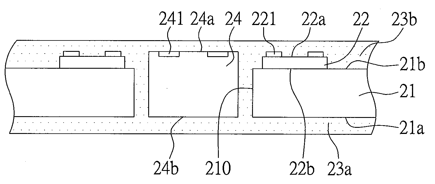
[0041]Please refer to FIGS. 2A through 2E, which are cross-sectional views of the first embodiment of a circuit board structure having an embedded semiconductor element and a fabrication method thereof according to the present invention.
[0042]As shown in FIG. 2A, first, providing a carrier board 21 that is either an insulating board or a ceramic plate, wherein the carrier board 21 has a first surface 21a, a second surface 21b, and at least one through hole 210 penetrating the carrier board from the first surface 21a to the second surface 21b; mounting at least one second semiconductor element 22 on the second surface 21b of the carrier board 21, wherein the second semiconductor element 22 has an active surface 22a and an inactive surface 22b and is mounted on the second surface 21b of the carrier board 21 via the inactive surface 22b, and the active surface 22a of the second semiconductor element 22 has a plurality of electrode pads 221; the second semiconductor element is either an...
second embodiment
[0050]Please refer to FIGS. 3A through 3E, which are cross-sectional views of the second embodiment of a circuit board structure having an embedded semiconductor element and a fabrication method thereof according to the present invention, the main difference from the first embodiment is that the carrier board of the second embodiment is a circuit board.
[0051]As shown in FIG. 3A, first provide a carrier board 21 that is a circuit board, the circuit board has a single-layered circuit or a multi-layered circuit, and the circuit board 21 has a first surface 21a, a second surface 21b, and at least one through hole 210 penetrating the carrier board from the first surface 21a to the second surface 21b; form a plurality of electrically connecting pads 211 on both the first surface 21a and the second surface 21b; next, mount a plurality of second semiconductor elements 22 and 22′ on the second surface 21b and the first surface 21a of the carrier board 21 respectively, the second semiconducto...
PUM
 Abstract
Description
Claims
Application Information
 - R&D
- Intellectual Property
- Life Sciences
- Materials
- Tech Scout
- Unparalleled Data Quality
- Higher Quality Content
- 60% Fewer Hallucinations
Browse by: Latest US Patents, China's latest patents, Technical Efficacy Thesaurus, Application Domain, Technology Topic, Popular Technical Reports.
© 2025 PatSnap. All rights reserved.Legal|Privacy policy|Modern Slavery Act Transparency Statement|Sitemap|About US| Contact US: help@patsnap.com


