Methods for enhancement of visibility of ablation regions

a technology of ablation region and enhancement method, which is applied in the field of diagnostic imaging, can solve the problems of increasing the risk of long-term exposure to ionizing radiation to the patient and medical personnel, affecting the visibility of ablation region, and affecting the safety of patients, so as to enhance the output signal, and enhance the visibility of the ablation region

Inactive Publication Date: 2008-06-26
GENERAL ELECTRIC CO
View PDF7 Cites 42 Cited by
  • Summary
  • Abstract
  • Description
  • Claims
  • Application Information

AI Technical Summary

Benefits of technology

[0007]In one embodiment of the present technique, a method for imaging during ablation procedures using ultrasound imaging is provided. The method includes obtaining input image data about an ablation region, wherein the image data comprises back scatter intensity, and applying a dynamic gain curve based on the image data to obtain an output signal for use in enhancing the visibility of the ablation region.
[0008]In another embodiment of the present technique, a method for enhancing the visibility of an ablation region during ablation procedures is provided. The method includes processing backscatter data from one or more image frames to identify changes in localized regions of image data, and applying a dynamic gain curve to obtain an enhanced output signal from the ablation region.
[0009]In yet another embodiment of the present technique, a method for in-situ enhancement of the visibility of an ablation region is provided. The method includes monitoring the ablation region, tracking a location of a catheter tip during ablation in the ablation region, analyzing a backscatter intensity in a predetermined region around the catheter tip, and adjusting the system settings to obtain enhanced backscatter data from the predetermined region.

Problems solved by technology

Heart rhythm problems or cardiac arrhythmias are a major cause of mortality and morbidity.
A drawback of these techniques however is that these procedures are extremely tedious requiring considerable manpower, time and expense.
Further, the long procedure times associated with the currently available catheter-based ablation techniques increase the risks associated with long term exposure to ionizing radiation to the patient as well as medical personnel.
Unfortunately, acquisition of the static map is very time consuming, and both the depicted anatomy and ablation locations are often inaccurate due to the dynamic nature of the beating heart.
However, these differences are often subtle and difficult to detect using conventional ultrasound imaging systems.

Method used


Image

  • Methods for enhancement of visibility of ablation regions
  • Methods for enhancement of visibility of ablation regions
  • Methods for enhancement of visibility of ablation regions

Examples


Embodiment Construction

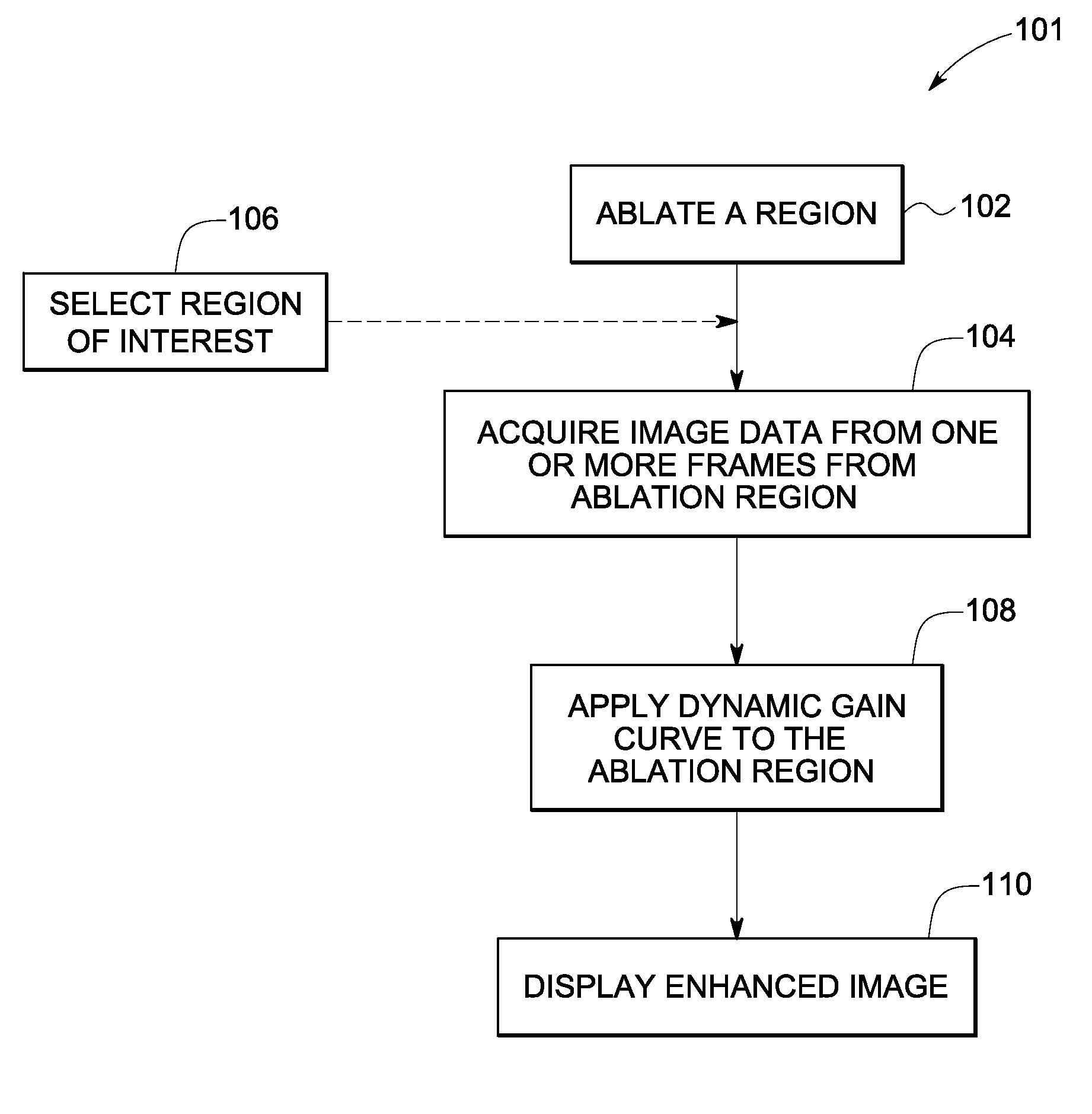
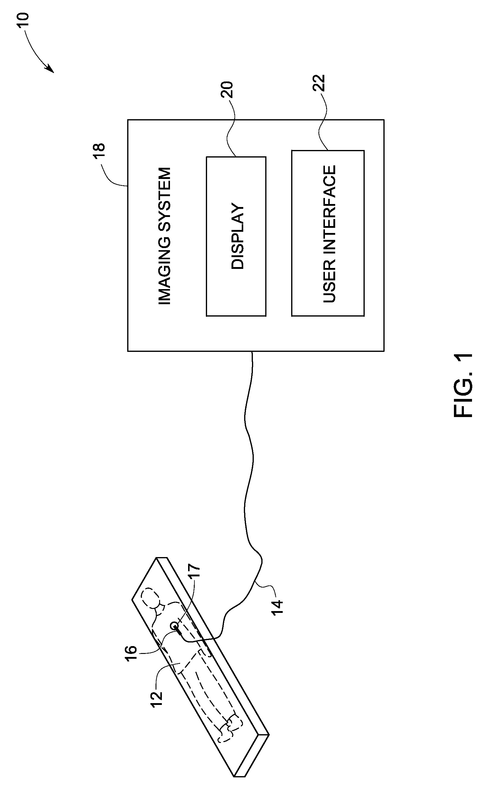
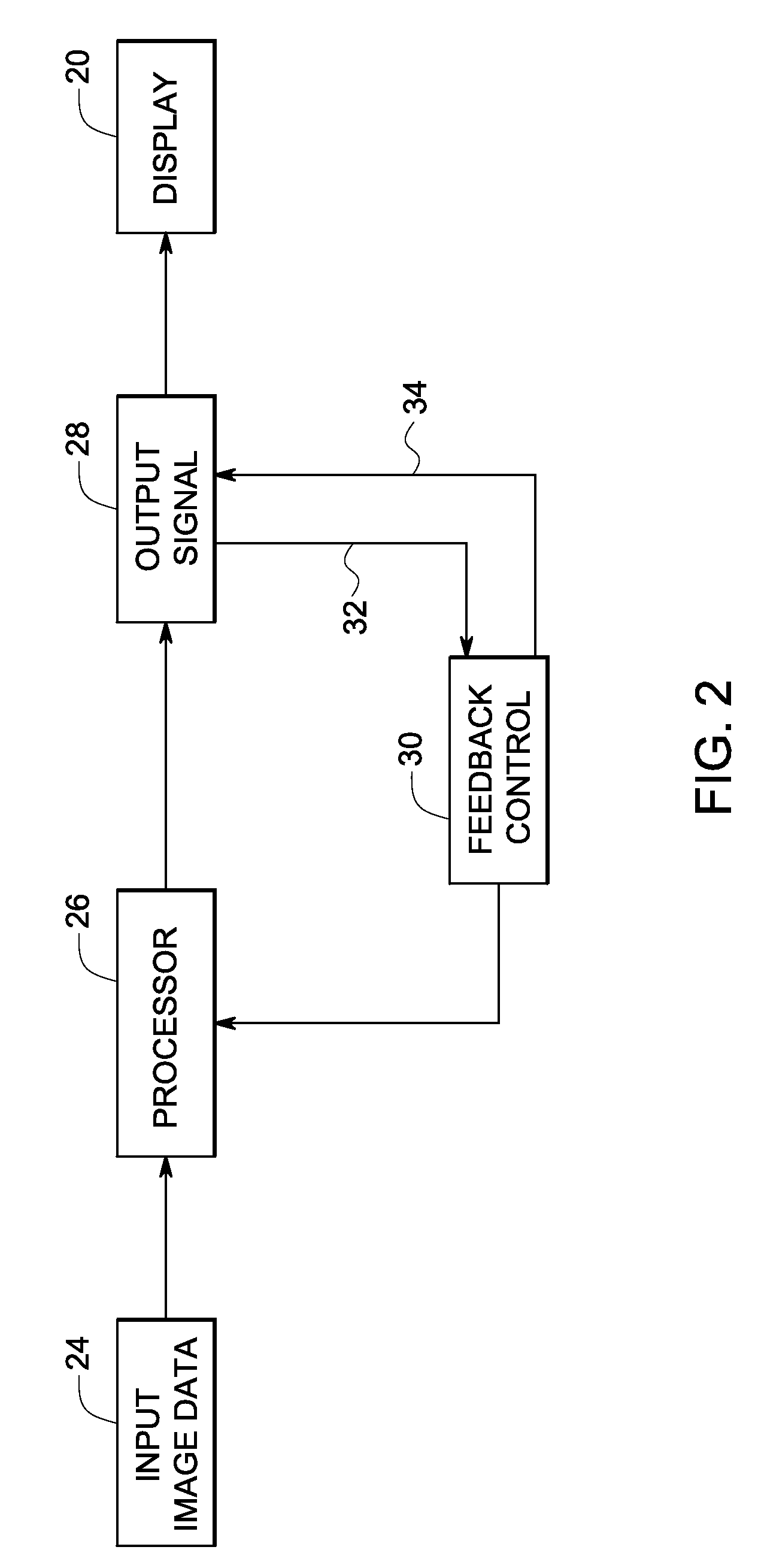
[0023]As will be described in detail hereinafter, ultrasound imaging systems and methods for real-time monitoring of ablation procedures and ablated regions in accordance with exemplary aspects of the present technique are presented. The systems and methods are configured to enhance visibility of the ablation regions in ultrasound imaging. As used herein, the term “ablation region” refers to a target volume affected by one or more of RF ablation, cryogenic ablation, chemical ablation, focused ultrasound beam, for example, employed to affect tissues in the target volume. Real-time, dynamic ablation monitoring systems represent a significant advancement beyond the static monitoring systems such as the CARTO electroanatomical mapping currently in use. The systems and methods described hereinafter may be employed in different types of ultrasound probes including intercardiac, transesophageal, transthoracic probes, and is applicable to all different types of ablation procedures using bot...


PUM


Abstract

A method for imaging during ablation procedures using ultrasound imaging is provided. The method includes obtaining input image data about an ablation region, wherein the image data comprises back scatter intensity, and applying a dynamic gain curve based on the image data to obtain an output signal for use in enhancing the visibility of the ablation region.

Description

BACKGROUND[0001]The invention relates generally to diagnostic imaging, and more particularly to enhancement of visibility in ablation regions.[0002]Heart rhythm problems or cardiac arrhythmias are a major cause of mortality and morbidity. Atrial fibrillation is one of the most common sustained cardiac arrhythmias encountered in clinical practice. Cardiac electrophysiology has evolved into a clinical tool to diagnose and treat these cardiac arrhythmias. As will be appreciated, during electrophysiological studies, multipolar catheters are positioned inside the anatomy, such as the heart, and electrical recordings are made from different locations inside the heart. Further, catheter-based ablation therapies have been employed for the treatment of atrial fibrillation.[0003]Conventional techniques utilize radio frequency (RF) catheter ablation for the treatment of atrial fibrillation. Currently, catheter placement within the anatomy is typically performed under fluoroscopic guidance. Int...

Claims


Application Information

Patent Timeline
Patent Type & Authority Applications(United States)
IPC IPC(8): A61B8/00
CPCA61B8/0841A61B8/12A61B18/1492G01S7/52033A61B2019/5276A61B2019/566A61N7/02A61B19/5244A61B34/20A61B2034/256A61B2090/378
Inventor LEE, WARRENSEYED-BOLORFOROSH, MIRSAIDDENTINGER, AARON MARKTHOMENIUS, KAI ERIK
Owner GENERAL ELECTRIC CO
Why Eureka
Try Eureka