Monitoring and fault detection in dynamic systems

a dynamic system and monitoring technology, applied in the field of data processing systems and methods, can solve the problems of control system driving the process into an undesirable and dangerous state, delay time stamps used as inputs to pca modules, and insufficient clarity of process dynamics, etc., to achieve the effect of easy implementation/return

Active Publication Date: 2008-06-26
HONEYWELL INT INC
View PDF15 Cites 23 Cited by
  • Summary
  • Abstract
  • Description
  • Claims
  • Application Information

AI Technical Summary

Benefits of technology

[0015]The system constructs a matrix of cross-correlation charts for one pair of tags using available training set data, constructs a matrix of lags between all variable pairs and calculates lag for one pair of tag variable by locating maximum of absolute value of cross-correlation function in chart. Then, the system calculates “cross-covariance” matrix using the matrix of lags and uses the calculated “cross-covariance” matrix in PCA instead of covariance matrix. The present invention can be more easily implemented / re-turned and configured in a more robust manner than prior art systems. Further, the present invention is more systematic and does not require manual data pre-processing steps.

Problems solved by technology

Traditional fault detection methods use model-based or knowledge-based approaches that require considerable effort to design and build, and incorporate analytical models or knowledge-based systems.
Abnormal situations commonly result from the failure of field devices such as instrumentation, control valves, and pumps or some form of process disturbance that causes the plant operations to deviate from the normal operating state.
In particular, the undetected failure of key instrumentation and other devices, which are part of the process control system, can cause the control system to drive the process into an undesirable and dangerous state.
Additionally, because time-series synchronization occurs in the context of a data pre-processing operation, the use of a snapshot monitoring method does not take into account the synchronization of time-series data corresponding to individual tags.
Moreover, delayed time stamps used as inputs to PCA modules are not sufficient for clearly capturing the process dynamics.

Method used


Image

  • Monitoring and fault detection in dynamic systems
  • Monitoring and fault detection in dynamic systems
  • Monitoring and fault detection in dynamic systems

Examples


Embodiment Construction

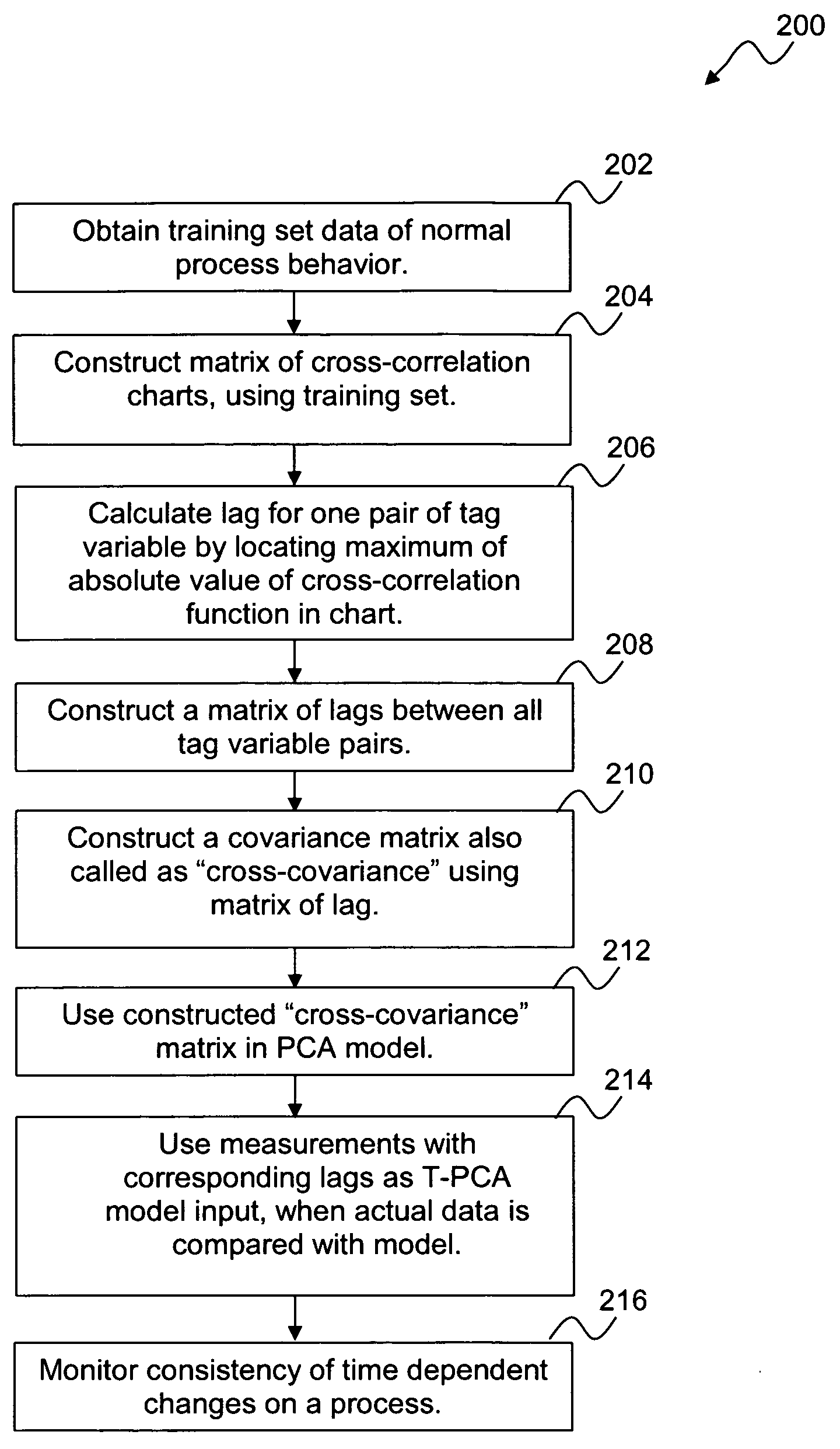
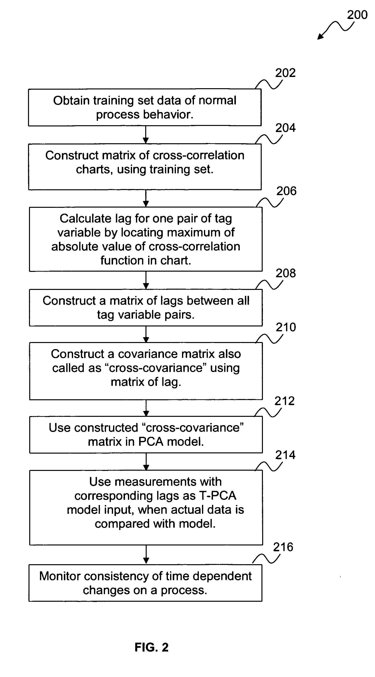
[0019]The particular values and configurations discussed in these non-limiting examples can be varied and are cited merely to illustrate at least one embodiment and are not intended to limit the scope thereof.

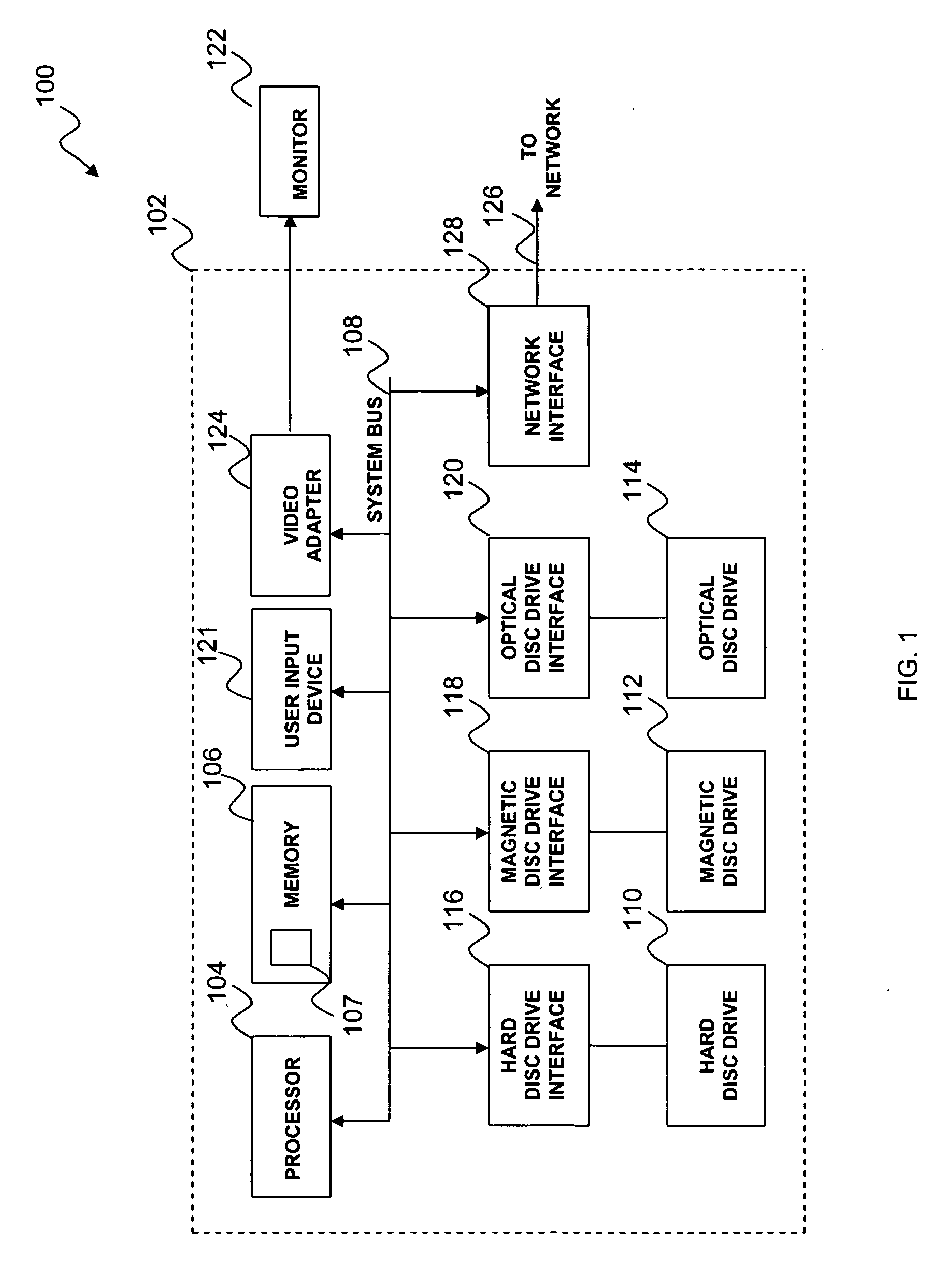
[0020]FIG. 1 illustrates a block diagram of a data-processing apparatus 100, which can be utilized to implement a preferred embodiment. Data-processing apparatus 100 can implement the present invention as described in greater detail herein. It can be appreciated that data-processing apparatus 100 represents merely one example of a system that can be utilized to implement the present invention described herein. System 100 is provided for general illustrative purposes only. Other types of data-processing systems can also be utilized to implement the present invention. Data-processing apparatus 100 can be configured to include a general purpose computing device, such as a computer 102. The computer 102 includes a processing unit 104, a memory 106, and a system bus 108 that operati...


PUM


Abstract

A system and method for monitoring and fault detection in dynamic systems. A “cross-covariance” matrix is used to construct and implement a principle component analysis (PCA) model and/or partial least squares (PLS) model. This system is further utilized for monitoring and detecting faults in a dynamic system. Time series information is synchronized, with respect to a set of training data. Based on historical data, consistency of correlations between variables can be checked with respect to a given time stamp. Temporal PCA (T-PCA) can be used for clearly monitoring changes in tags (time series) synchronization, even when the temporal behaviors of the dynamic system are not clear.

Description

TECHNICAL FIELD[0001]Embodiments are generally related to data-processing systems and methods. Embodiments are also related to techniques for monitoring a continuous manufacturing system. Embodiments are additionally related to systems and methods for monitoring and detecting faults in dynamic systems.BACKGROUND OF THE INVENTION[0002]Traditional fault detection methods use model-based or knowledge-based approaches that require considerable effort to design and build, and incorporate analytical models or knowledge-based systems. In order to address the difficulties that lie in model-based or knowledge-based methods, model-free statistical process monitoring (SPM) techniques have been developed, which require only a good historical data set of normal operations. In current manufacturing and industrial processes, massive amounts of trace or machine data are generated and recorded. Because of the high dimensionality of the data, both principal component analysis (PCA) and partial least ...

Claims


Application Information

Patent Timeline
Patent Type & Authority Applications(United States)
IPC IPC(8): G06F15/00
CPCG05B23/024
Inventor NAVRATIL, ROMAN
Owner HONEYWELL INT INC
Why Eureka
Try Eureka