
Combustion analyzer sample introduction apparatus and method

a sample introduction and sample technology, applied in the direction of instruments, material heat development, transportation and packaging, etc., can solve the problems of increasing the heat evolution rate, reducing the number of separate components, so as to reduce or avoid evaporation and residue formation, the effect of avoiding the blocking of the sample introduction apparatus

Inactive Publication Date: 2008-07-03
THERMO ELECTRON MFG
View PDF16 Cites 1 Cited by
  • Summary
  • Abstract
  • Description
  • Claims
  • Application Information

AI Technical Summary

Benefits of technology

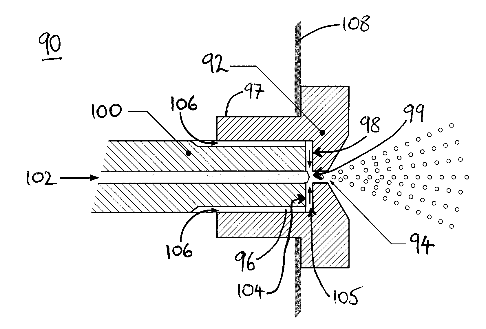
[0018]Where the sample supply conduit and the carrier gas supply conduit meet, a flow of sample will be disrupted by the carrier gas. The carrier gas will break up the sample flow and entrain the sample. The sample will then be discharged from the supply head as a fine mist or spray. A sample may therefore be supplied as a spray directly into a combustion chamber. Since the sample droplets formed in the spray are of relatively small size, during their combustion not enough heat is generated to create local hotspots, so that undesirable, high-temperature oxidation reactions and local oxygen deficiencies leading to soot formation can be avoided.
[0032]In a preferred embodiment, the sample supply conduit is modified to accept the sample supply tube of an autosampler. The internal diameter of the sample supply conduit is sized to allow the autosampler supply tube to pass into it, as far as a stopping portion, of reduced internal diameter. This allows for a reduction in the number of rinsing steps between samples and can help to reduce cross-contamination between samples.

Problems solved by technology

While both techniques have their uses, each is subject to a number of limitations and disadvantages.
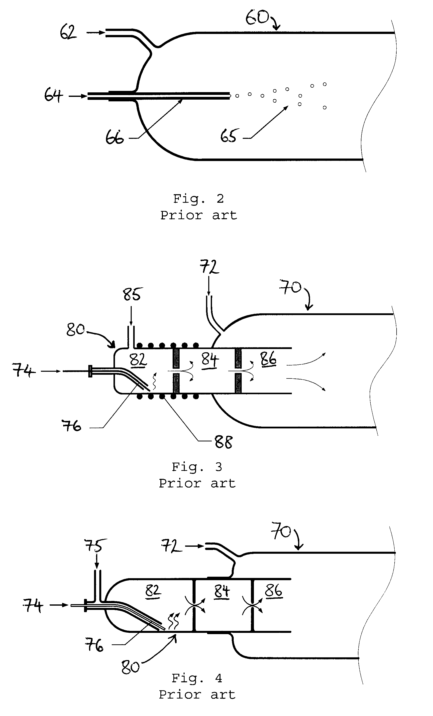
However, if organic samples are injected into the hot, oxygen-rich combustion chamber 60, the relatively large sample droplets will each burn vigorously, leading to a locally increased rate of heat evolution, resulting in hotspots at very high temperatures, of possibly more than 1500° C. These hotspots can result in undesirable oxidation reactions taking place in the combustion chamber 60, such as the combustion of traces of nitrogen gas into NOx, or sulphur into SO3.
Such undesirable combustion products lead to faulty analysis results.
Furthermore, the combustion of large sample droplets can result in local oxygen deficiencies, leading to regions of incomplete combustion.
This causes soot, or heavy residue, to be produced which can contaminate the downstream gas conditioner and detectors.
However, using a catalyst has many disadvantages, including loss of effectiveness (through degradation over time and contamination from samples) and selectivity (promotion of the oxidation of some components better than others), so that catalysts need to be replaced regularly and analyzers need to be calibrated frequently.
Another disadvantage of the direct injection technique is that the injection needle 66 can become blocked.
Evaporation of the liquid sample 64 inside the injection needle 66 may take place and dissolved solids in the sample can then be deposited as a residue on the inside of the needle, eventually leading to needle blockage and analyzer failure.
Although the vapour introduction technique addresses the hotspot problem, it still suffers from a number of disadvantages.
The technique is limited to samples which may be fully converted into the gas phase by evaporation or thermal cracking, under the given conditions.
Thus, a sample, which contains or produces (by condensation) heavy components, such as those having boiling points above 450° C., cannot be handled.
In addition, although less severe compared with the direct injection technique, sample evaporation and consequent blocking in the injection needle 76 is still a problem, especially with “dirty” samples.
Furthermore, the use of argon is costly and acts to dilute the combustion gases, thereby impairing the subsequent analysis.

Method used


Image

  • Combustion analyzer sample introduction apparatus and method
  • Combustion analyzer sample introduction apparatus and method
  • Combustion analyzer sample introduction apparatus and method

Examples


Embodiment Construction

[0046]Referring to FIG. 5, there is shown a sample introduction apparatus 90 according to one embodiment of the invention. The sample introduction apparatus 90 acts as a spray injector, to discharge a liquid sample therefrom in the form of a spray or mist. The sample introduction apparatus 90 comprises a spray head 92, which has a spray, or discharge, opening 94 extending axially through a downstream, combustion chamber-facing part of the spray head. On an upstream, sample supply-facing part of the spray head 92 is formed a cylindrical cavity 96, which has a flat front wall 98. A supply inlet 99 formed at the centre of the front wall 98 provides a fluid communication path between the cavity 96 and the spray opening 94.

[0047]The sample introduction apparatus 90 also comprises a sample supply tube 100 having a channel 102 running therethrough. The tube 100 has an annular-profiled, downstream end 104, which extends in the cavity 96 towards the front wall 98. A disc-shaped gap 105 is fo...


PUM


Abstract

A combustion analyzer sample introduction apparatus and method for supplying a liquid sample into a combustion chamber (130,150) of a combustion analyzer. A supply member (108, preferably, cooled) extends through a combustion chamber opening (132,152) and comprises a downstream member end within the combustion chamber. A supply spray head (92) is received in the member end and comprises a discharge opening (94) to deliver liquid sample and carrier gas into the combustion chamber. A carrier gas supply conduit (106,114,122) supplies carrier gas (preferably, oxygen) to the discharge opening, along a carrier gas flow path. A sample supply conduit (100,102) having a downstream first end passes through the supply member towards the spray head and supplies liquid sample into the carrier gas flow path at a sample supply location within the combustion chamber at / adjacent the discharge opening. Liquid sample is thereby transported by carrier gas out of the discharge opening into the combustion chamber as a spray.

Description

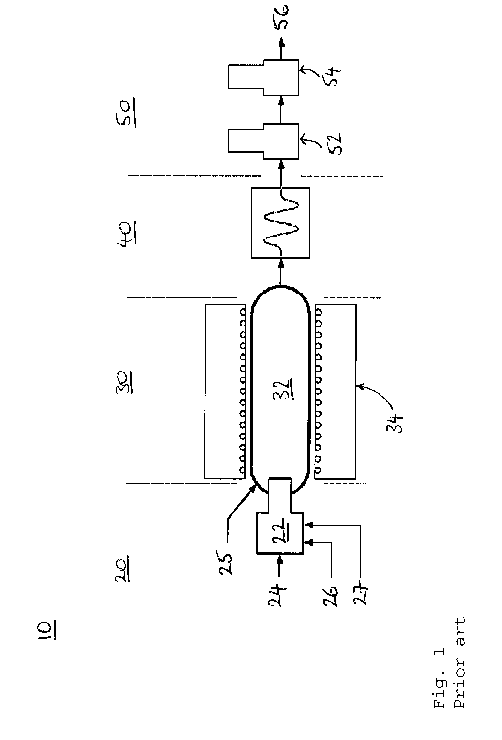
CROSS REFERENCE[0001]This application claims priority benefit of Great Britain Patent Application Number 0625938.6, filed Dec. 29, 2006.FIELD OF THE INVENTION[0002]The invention relates to a combustion analyzer sample introduction apparatus and method. In particular, the sample introduction apparatus and method are for introducing a liquid sample into a combustion analyzer.BACKGROUND OF THE INVENTION[0003]Combustion analyzers are used to determine the concentration of one or more components of a liquid sample, by combusting the sample and analysing the gaseous products for specific oxides. Typically, the carbon, sulphur and / or nitrogen content of the sample is measured by detecting CO2, SO2 and NOx, respectively.[0004]A schematic illustration of a typical combustion analyzer is shown in FIG. 1. The combustion analyzer 10 comprises a sample introduction stage 20, a combustion stage 30, a conditioning stage 40, and a detection stage 50. The sample introduction stage 20 comprises a sam...

Claims


Application Information

Patent Timeline
IPC IPC(8): G01N7/06
CPCG01N31/12B05B1/02G01N25/24B01F25/30
Inventor SMEETS, LOUIS MARIEVAN DER ZALM, MARINUS ARNOLDUS WILHELMUS
Owner THERMO ELECTRON MFG
Learn More