Brake System With Redundancy

a brake system and redundancy technology, applied in the direction of brake systems, mechanical equipment, transportation and packaging, etc., can solve the problems of limiting the time for keeping up the brake function, increasing the resistance loss, and limiting the effect of the brake function, so as to achieve the effect of simple manner and weight-saving cost advantages

Inactive Publication Date: 2008-07-03
HALDEX BRAKE PROD AB
View PDF16 Cites 6 Cited by
  • Summary
  • Abstract
  • Description
  • Claims
  • Application Information

AI Technical Summary

Benefits of technology

[0007]a) Two separate motors with two separate shafts and a rotational speed reduction to a brake pad. The brake pad may be arranged slidably in relation to a ramp in a self-energizing disc brake as shown in WO 03 / 071150. In a self-energizing brake it is optimal to dimension the slope of the ramp so that the friction number is close to the number giving theoretical indefinite self-energization. A mechanical slack—together with the characteristics that a self-energizing brake has in this range—create control problems. By having the two motors working “against” each other at these occasions, the slack may be eliminated without costly mechanical solutions for slack minimizing.
[0009]c) One motor package with thermally and electrically insulated winding packets in the stator portion and a common rotor on a common shaft. Each coil winding can per se perform the function of one motor with the drawback that the loss resistances increase with the decreasing copper volume and thus increase resistive losses, which may limit the time for keeping up the brake function or may limit the effect of the brake function during an indefinite time.
[0012]According to one aspect of the present invention the power needed to actuate the brake is very low, meaning that the power may be produced in a simple manner giving advantages both regarding weight and cost.

Problems solved by technology

a) Two separate motors with two separate shafts and a rotational speed reduction to a brake pad. The brake pad may be arranged slidably in relation to a ramp in a self-energizing disc brake as shown in WO 03 / 071150. In a self-energizing brake it is optimal to dimension the slope of the ramp so that the friction number is close to the number giving theoretical indefinite self-energization. A mechanical slack—together with the characteristics that a self-energizing brake has in this range—create control problems. By having the two motors working “against” each other at these occasions, the slack may be eliminated without costly mechanical solutions for slack minimizing.
b) Two separate motors with two separate shafts and partly common mechanical transmission to the pad ramp.
c) One motor package with thermally and electrically insulated winding packets in the stator portion and a common rotor on a common shaft. Each coil winding can per se perform the function of one motor with the drawback that the loss resistances increase with the decreasing copper volume and thus increase resistive losses, which may limit the time for keeping up the brake function or may limit the effect of the brake function during an indefinite time.

Method used


Image

  • Brake System With Redundancy
  • Brake System With Redundancy
  • Brake System With Redundancy

Examples


Embodiment Construction

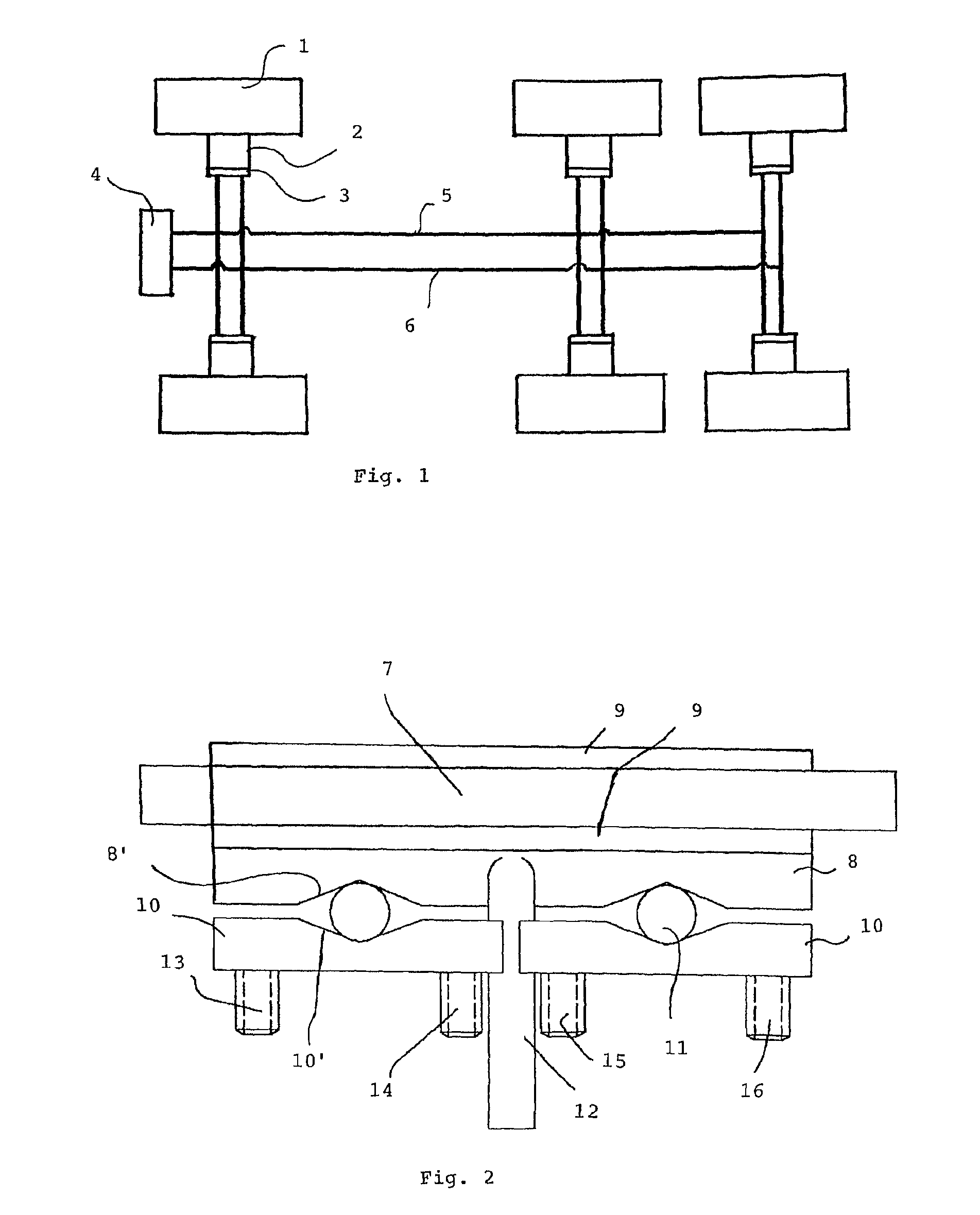
[0019]In FIG. 1 one example of a network topology is shown. The shown embodiment is directed to the control function, but a person skilled in the art realizes that the voltage supply part has a similar design.

[0020]In the shown embodiment six disc brakes 1 are shown, but a person skilled in the art realizes that any number of brakes may be used. Each disc brake 1 is actuated by means of a drive unit controlled by an electronic control unit 3. The drive unit comprises at least two separate, cooperating drive units 2. The electronic control unit 3 of each brake 1 is connected to a vehicle control unit 4. As a safe guard the separate electronic control units 3 and the vehicle control unit 4 are connected by means of two separate nets 5, 6. All control units 3, 4 are connected to both nets 5, 6 and thus, even if one net fails the control of the brakes 1 will function by means of the other net.

[0021]For the voltage supply to the drive units 2 of each brake 1 two power supplies are provid...


PUM


Abstract

The present invention concerns a brake system creating redundancy in electromechanical brakes. At least two drive units are provided at each single brake for activation of the brake. The at least two units may be controlled and / or energized separately. To safeguard the function the control and / or energy source systems are formed in two nets. The at least two units of each brake are connected to separate nets. The at least two units may be separate electrical motors.

Description

CROSS-REFERENCE TO RELATED APPLICATIONS[0001]This application is a continuation-in-part of U.S. patent application Ser. No. 11 / 388,564, filed Mar. 24, 2006, currently pending, which is a continuation of International Patent Application No. PCT / SE2004 / 001383 filed on Sep. 27, 2004, which designates the United States and claims priority of Swedish Patent Application No. 0302562-4 filed on Sep. 26, 2003.FIELD OF THE INVENTION[0002]The present invention relates to creating redundancy in an electromechanical brake by using at least two units giving actuating force in each separate brake. The solution can be used in an environment where electric energy is regarded as equally safe as mechanical energy (for example in the form of energy stored in a spring in a so called spring brake) in an application where safety is critical. In systems where safety is critical, the safety at catastrophic failures today most often depends on mechanical energy from application springs (spring braking).BACKG...

Claims


Application Information

Patent Timeline
Patent Type & Authority Applications(United States)
IPC IPC(8): B60T1/06F16D65/14F16D55/22
CPCF16D65/18F16D65/568F16D2127/10F16D2123/00F16D2121/24
Inventor NILSSON, PETER
Owner HALDEX BRAKE PROD AB
Why Eureka
Try Eureka