Differential pressure sensing device and fabricating method therefor

a sensing device and different technology, applied in the direction of fluid pressure measurement, fluid pressure measurement by electric/magnetic elements, instruments, etc., can solve the problems of large scale of cell phone application market, large application field and scope of device, and high overall cost of devi

Inactive Publication Date: 2008-07-03
IND TECH RES INST
View PDF5 Cites 27 Cited by
  • Summary
  • Abstract
  • Description
  • Claims
  • Application Information

AI Technical Summary

Benefits of technology

[0011]In view of the above disadvantages, the present invention is a method of fabricating a plastic package of a differential pressure sensing device and a structure thereof, such that when the window is opened above the active area of the differential pressure sensing device, the layer can be naturally decomposed, which will not contaminate the environment and damage the original molding material.
[0015]The functions of the implementation of the embodiments of the present invention are described as follows. When the window is opened above the active region of the surface of the differential pressure sensing device, no pad is required, such that the manufacturing method is greatly simplified. The integral processing can be adopted to open window on a plurality of differential pressure sensing devices, thus greatly improving the throughput and increasing the yield of the open window process. In the present invention, no strong acid spray etching process is used, so the problems that the acid etching parameters and etching time cannot be easily controlled and the environmental pollution and industrial safety accident occur due to the acid liquor leakage are eliminated. Also, in the present invention, a through-hole corresponding to the recess of the differential pressure sensing device is further disposed on the carrier, such that it can be used together with the differential pressure sensing device having particular functions to provide particular functions. In addition, in the present invention, during the open window process, the part outside of the active region of the differential pressure sensing device will not be affected, thus preventing the occurrence of poor electrical coupling of the bonding pads of the differential pressure sensing device and the carrier.

Problems solved by technology

However, the overall cost of the device is high, so the application fields and scope of the device is greatly reduced.
Therefore, the scale of the application market of the cell phone is quite large.
Unfortunately, impelled by the light in weight and small in size” requirement, the volume of the cell phone cannot be increased with the increase of the functions of the cell phone.
Further, due to the sale point of light and chic, the size of the cell phone may be limited in a certain scope, and even the profile is further reduced.
On the other hand, the cell phone is a common product in the global market, so the overall cost will be limited in a reasonable scope, and cannot be sold at high unit price like high-tech instruments or fittings.
The overall cost of the elements installed in the cell phone will challenge the design.
However, the process of the differential sensing device package 10 of the conventional art has obvious defects.
The strong acid process needs additional acid etching pads, and it is not easy to control the acid etching parameters, such that the yield is not high and also the problems of industrial safety and environment pollution exist.

Method used


Image

  • Differential pressure sensing device and fabricating method therefor
  • Differential pressure sensing device and fabricating method therefor
  • Differential pressure sensing device and fabricating method therefor

Examples


Embodiment Construction

[0028]The preferred embodiments of the present invention will be illustrated in detail in accompanying with the drawings.

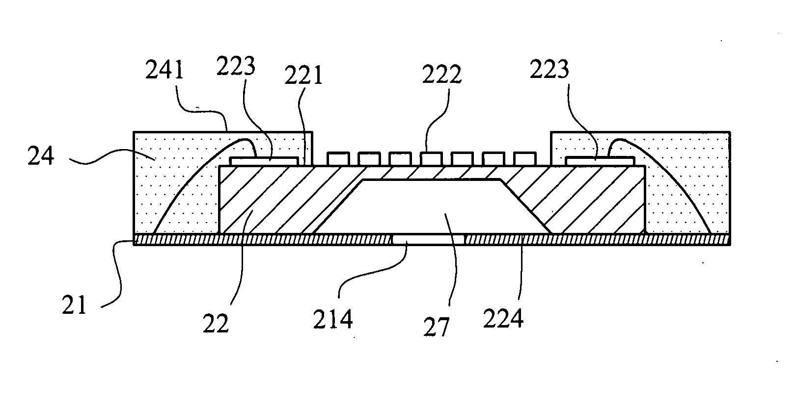
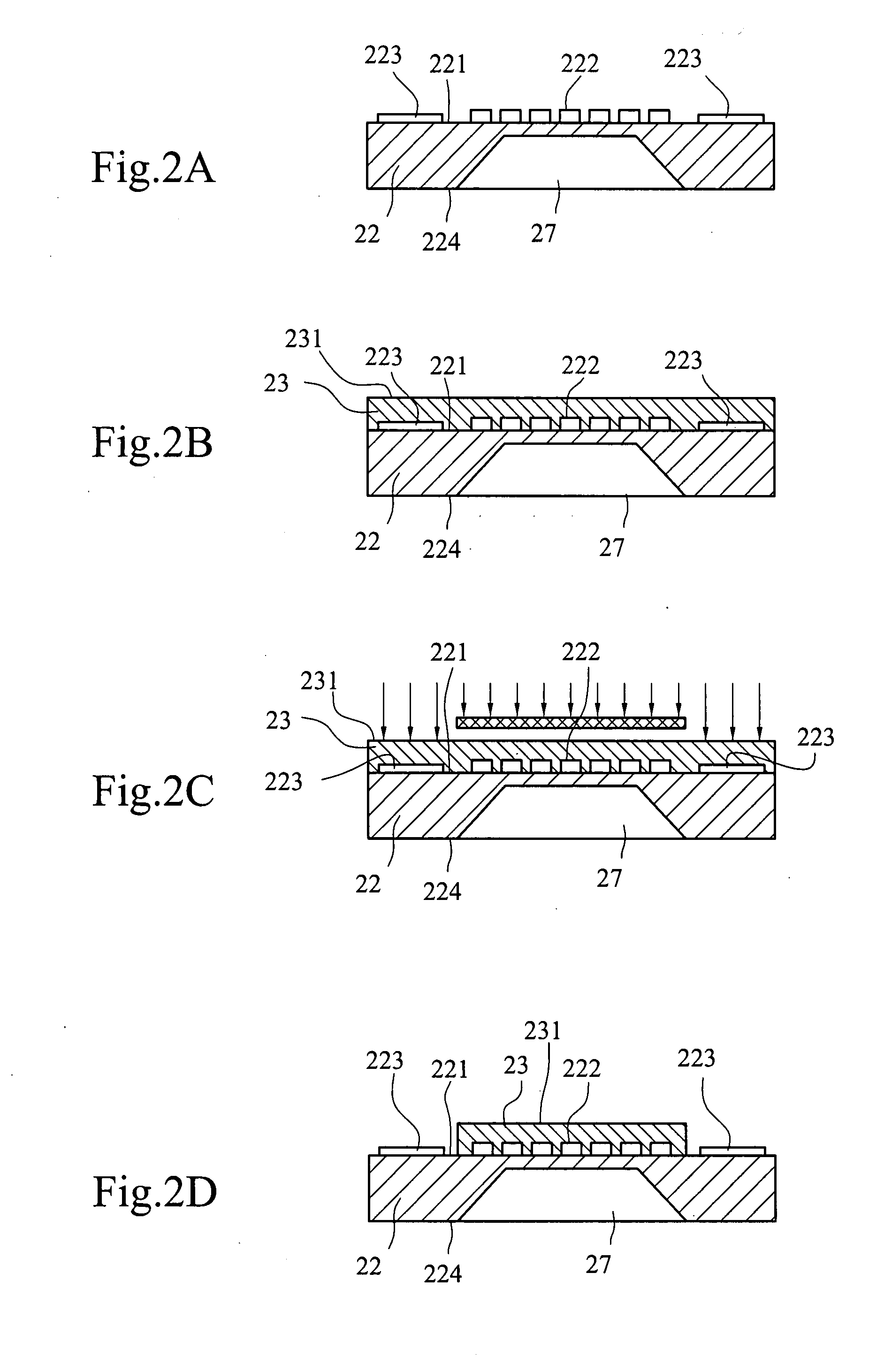
[0029]Referring to FIGS. 2A to 2G, the fabricating method includes the following steps. Firstly, a plurality of differential pressure sensing devices 22 each having an active surface 221 and a back surface 224 is provided. The active surface 221 has an active region 222 and a plurality of bonding pads 223, and the back surface 224 has a recess 27.

[0030]After that, a photoresist process is performed to form a sacrificial layer 23 on the active region 222, so as to avoid damaging the active region 222 during the subsequent molding operation. The sacrificial layer 23 may be a photosensitive high molecular material, such as SU-8 photoresist. The method of coating the active region is a spin coating method to form a photoresist layer (i.e. the sacrificial layer 23) with a uniform thickness or a screen printing method using the screen mask.

[0031]Next, a carrier 21 havin...


PUM


Abstract

At least one differential pressure sensing device has an active surface with an active region and a back surface with a recess. Next, a sacrificial layer is formed on a surface of the active region. Then, the differential pressure sensing device is bonded and electrically coupled with a surface of a carrier that has at least one through-hole corresponding to the recess of the differential pressure sensing device. Afterwards, at least one molding compound is formed to encapsulate the carrier and differential pressure sensing device while exposing the through-hole region and an upper surface of the sacrificial layer. Then, a solvent is used to naturally decompose the sacrificial layer, such that the active region of the differential pressure sensing device is exposed to atmosphere, thereby forming a differential pressure sensing device package with the through-hole.

Description

CROSS-REFERENCE TO RELATED APPLICATIONS[0001]This non-provisional application claims priority under 35 U.S.C. § 119(a) on Patent Application No(s). 095150069 filed in Taiwan, R.O.C. on Dec. 29, 2006, the entire contents of which are hereby incorporated by reference.BACKGROUND OF THE INVENTION[0002]1. Field of Invention[0003]The present invention relates to a differential pressure sensing device package and a fabricating method therefor. More particularly, the present invention relates to a fabricating method of forming a space on an active region of a differential pressure sensing device in a package and a structure thereof.[0004]2. Related Art[0005]For current micro electromechanical system (MEMS) industry, sensing devices have inherent characteristics of being miniaturized and integrated. However, the overall cost of the device is high, so the application fields and scope of the device is greatly reduced. Under the influence of the personalization and popularity of global communic...

Claims


Application Information

Patent Timeline
Patent Type & Authority Applications(United States)
IPC IPC(8): H01L29/84H01L21/56
CPCG01L19/141H01L23/3185H01L2924/1461H01L2224/45144H01L2924/1815H01L2224/32245H01L2224/73265H01L2224/48247H01L2224/48091G01L9/0042H01L2924/00014H01L2924/00H01L2924/12044H01L2924/00012
Inventor CHEN, JUNG-TAICHU, CHUN-HSUNSHIEH, WEN-LO
Owner IND TECH RES INST
Why Eureka
Try Eureka