Voltage monitor circuit

a voltage monitor and circuit technology, applied in the direction of parallel/serial switching, indicating/monitoring circuits, transportation and packaging, etc., can solve the problem of reducing the risk that the monitor circuit mistakenly detects a voltage due to noise or the lik

Inactive Publication Date: 2008-07-03
HONDA MOTOR CO LTD
View PDF8 Cites 26 Cited by
  • Summary
  • Abstract
  • Description
  • Claims
  • Application Information

AI Technical Summary

Benefits of technology

[0019]Under these configurations, the solid state switch which is turned on in response to a negative voltage is turned on in response to an electric potential of a wire adjoining on the side of a low electric potential. For example, if a P-channel MOSFET is used as a solid state switch, the P-channel MOSFET can be turned on in response to a signal from a wire adjoining on the side of a low electric potential. Therefore, the current breaking switch connected in series between optional electric storage cells is turned off, the P-channel MOSFETs interposed in wires on the side of a higher electric potential than an electric potential of the current breaking switch are turned off. As a high voltage generated across both terminals of the current breaking switch at a time of turning off the current breaking switch is distributed to all the P-channel MOSFETs which relevantly change into an OFF state, a risk that a high voltage is generated between input terminals of the monitor circuit is reduced.
[0020]According to the present invention, an application of a high-voltage for a monitor circuit can be avoided even if a series circuit of an electric storage cell is cut off by a current breaking switch.

Problems solved by technology

Further, as parasitic capacitance between wires is connected in parallel with a resistance element, a risk that the monitor circuit mistakenly detects a voltage due to noise or the like is reduced.

Method used


Image

  • Voltage monitor circuit
  • Voltage monitor circuit
  • Voltage monitor circuit

Examples


first embodiment

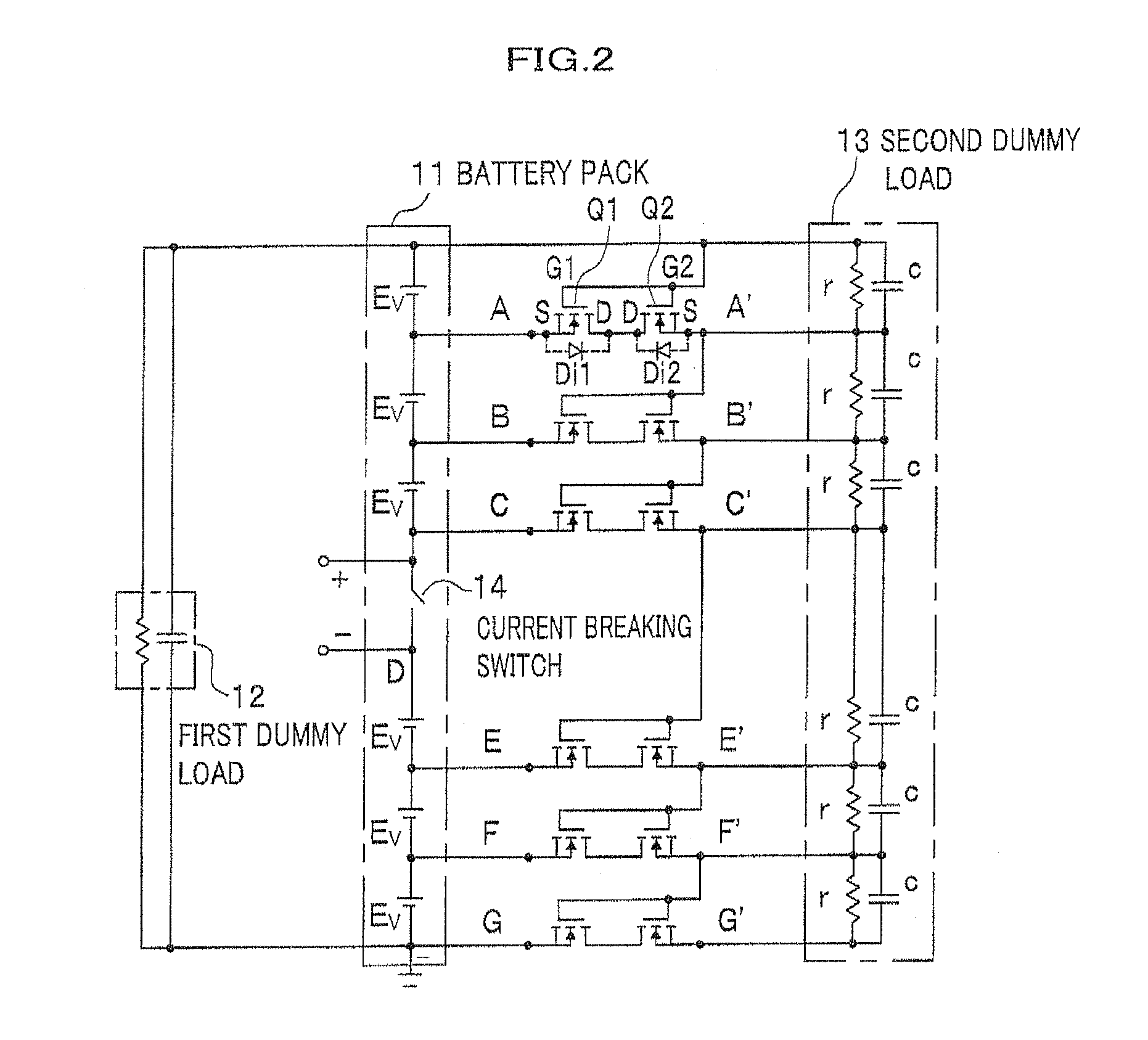
[0037]A first embodiment is a concrete embodiment in which an N-channel MOSFET interposed in wires detecting a voltage of each battery constituting a battery pack is used as a two-way current-carrying solid state switch.

[0038]FIG. 2 is a circuit diagram showing a power supply circuit of a hybrid vehicle which includes a voltage monitor circuit of the first embodiment of the present invention. As shown in FIG. 2, as for the power supply circuit of the first embodiment, an N-channel MOSFET is interposed between wires connecting each battery of a battery pack 11 with a monitor circuit (a second dummy load 13). Incidentally, In FIG. 2, a drain terminal D, a source terminal S and gate terminals G1 and G2 of the N-channel MOSFET (hereinafter referred as a FET) are illustrated with a mark. Then, a pair of FETs from among FETs opposite to each other in series is marked with Q1 and Q2 for convenience sake. Further, each FET has a parasitic diode. To make a better understanding, only a diode ...

second embodiment

[0047]In the first embodiment, as for the second dummy load 13 making up of an equivalent circuit of the monitor circuit, each voltage detection circuit is a CR parallel circuit, so that a period of time during which the point C′ has a negative voltage after turning off the current breaking switch 14 and an electric potential at each point E′, F′, and G′ assumes an almost same negative electric potential as the point C′ is delayed, depending on time constant of the CR parallel circuit. In a second embodiment, a voltage monitor circuit which takes this malfunction of time delay into consideration is suggested.

[0048]In a circuit diagram shown in FIG. 4, a diode Di is connected in parallel with each CR parallel circuit of a second dummy load 13 making up of an equivalent circuit of the monitor circuit.

[0049]Consequently, as the diode Di is connected in parallel with CR parallel circuit, the wire C′ has a negative voltage after turning off the current breaking switch 14. When FETs inter...

third embodiment

[0051]In a third embodiment, an embodiment in which a P-channel MOSFET (hereinafter referred as a FET) as a two-way current-carrying solid state switch interposed in a wire detecting a voltage of each battery making up of a battery pack is used is explained. FIG. 5 is a circuit diagram showing a power supply circuit for a hybrid vehicle having a voltage monitor circuit in the third embodiment of the present invention. As shown in FIG. 5, in the power supply circuit of the third embodiment, a P-channel FET which is turned on with a negative voltage on a gate terminal is used as a solid state switch interposed in a wire of the power supply circuit of the battery pack.

[0052]As shown in FIG. 5, when a P-channel F′ET is used, two sets of P-channel FETs are connected opposite to each other in series in order to flow a current in both directions with each wire except for a wire with a minimum electric potential (that is, the wire on the bottom of the figure). Further, the gate terminals G1...


PUM


Abstract

A voltage monitor circuit, wherein a high voltage is not applied to a monitor circuit even if a series circuit of plural batteries connecting a battery pack is cut off, is provided. When a current breaking switch is turned off, a high series voltage with reversed polarity of plural batteries is generated across the current breaking switch. Subsequently, a solid state switch with a negative voltage is turned off. Further, as a wire on the side of a battery pack monitor circuit also has a negative voltage, another solid state switch biased by a voltage of the wire is turned off likewise. Consequently, a high voltage is not generated between the wires on the side of the battery pack monitor circuit even if the current breaking switch is turned off.

Description

CROSS-REFERENCE TO RELATED APPLICATION(S)[0001]This application claims the foreign priority benefit under Title 35, United States Code, § 119 (a)-(d), of Japanese Patent Application No. 2006-348454, field on Nov. 25, 2007 in the Japan Patent Office, the disclosure of which is herein incorporated by reference in its entirety.BACKGROUND OF THE INVENTION[0002]1. Field of the Invention[0003]The present invention relates to a voltage monitor circuit which monitors a voltage of a storage unit, wherein capacitors are connected in series.[0004]2. Description of the Related Art[0005]In a hybrid vehicle and the like, a great number of batteries are connected in series as a battery pack and stored in a battery box. The battery pack generates a high voltage and an inverter used for driving a motor is operated by a direct current. A voltage of each battery is always monitored by a monitor circuit. Further, batteries in series are divided into about half segments where a current breaking switch a...

Claims


Application Information

Patent Timeline
Patent Type & Authority Applications(United States)
IPC IPC(8): H02J7/00
CPCY02T10/7055H02J7/0021Y02T10/70H02J7/0048H02J7/0024
Inventor OHNUKI, YASUMICHI
Owner HONDA MOTOR CO LTD
Why Eureka
Try Eureka