
Multicarrier transmission method, multicarrier modulation signal transmission apparatus, multicarrier modulation signal reception apparatus, multicarrier modulation signal transmission method, and pilot signal generation method

Active Publication Date: 2008-07-03
REDWOOD TECHNOLOGIES LLC
View PDF10 Cites 14 Cited by
  • Summary
  • Abstract
  • Description
  • Claims
  • Application Information

AI Technical Summary

Benefits of technology

[0051]Therefore, an object of the present invention is to estimate the transmission channel characteristics using a pilot carrier with a high level of frequency efficiency and a high level of precision of estimation of transmission channel characteristics in the OFDM / OQAM multicarrier modulation scheme.
[0053]According to the present invention, the number of subcarriers used as pilot carriers is one, so that the frequency efficiency can be improved. In addition, since the distance between the ideal demodulation vectors of pilot signals of two successive symbols in the time direction can be maximized, the precision of estimation of transmission channel characteristics can be improved.

Problems solved by technology

In wireless mobile communications, multipath propagation often disadvantageously occurs, i.e., a plurality of incoming transmission signals which are variously delayed due to reflection of radio waves are received.
However, in OFDM / QAM, the guard interval is only used for toleration of multipath propagation, but no effective information is transmitted during the guard interval.
Therefore, OFDM / QAM disadvantageously has low spectral efficiency or otherwise loss.
Also in OFDM / QAM, when a delay time difference due to multipath propagation exceeds the guard interval, transmission quality is rapidly deteriorated, resulting in an insufficient effect of filtering a narrow-band interference signal.
However, in OFDM / OQAM, a modulation signal in which pilot signals are freely arranged in units of one symbol and one subcarrier cannot be used, as is similar to OFDM / QAM.
Therefore, the receiver cannot obtain the amount of a change between the ideal demodulation vector of the pilot signal and a demodulation vector of an actually received pilot signal, as is similar to OFDM / QAM, so that transmission channel characteristics cannot be correctly estimated.
Therefore, the ideal demodulation vector of the pilot signal is invariably interfered with by an uncertain imaginary-axis component due to preceding and succeeding OFDM / OQAM multicarrier modulation signals.
When the distance between demodulation vectors of two pilot signals is small, a demodulation error between the points Rm and Rm+1 has a significant influence on the slope of the straight line L1, so that, particularly, the precision of estimation of the amount of a change in phase is deteriorated.
However, since a transmission data signal cannot be inserted during transmission of a continuous pilot signal, frequency efficiency is deteriorated.
Also, when a time required to modulate all subcarrier with the same pilot signal is short, the distance between the ideal demodulation vectors of pilot signals of two adjacent subcarriers at the same time may be small, so that the precision of estimation of transmission channel characteristics is deteriorated.
Meanwhile, there is a large variation in the estimated value of transmission channel characteristics calculated for each symbol, and there is also a large error.
Therefore, as compared to the first method of Patent Document 1, the frequency efficiency is improved, but the precision of estimation of transmission channel characteristics is reduced and there is a large variation in the estimated value and there is also a large error.
Therefore, the precision of estimation of transmission channel characteristics is deteriorated.
Also, when there is even a small interference component from an OFDM / OQAM multicarrier modulation signal of a subcarrier adjacent to a pilot carrier, it is difficult to fix the demodulation vector of the pilot signal completely to a single point, and therefore, the precision of estimation of transmission channel characteristics is deteriorated.
In this case, however, the number of subcarriers which cannot be used for data transmission increases, the frequency efficiency is further reduced.
However, even when such a combination technique is used, the problem with Patent Document 2 that at least two adjacent subcarriers are required to generate a pilot carrier, and the problem with the second method of Patent Document 1 that the precision of estimation of transmission channel characteristics is reduced due to the small distance between demodulation vectors of pilot signals of two adjacent subcarriers, cannot be solved.

Method used


Image

  • Multicarrier transmission method, multicarrier modulation signal transmission apparatus, multicarrier modulation signal reception apparatus, multicarrier modulation signal transmission method, and pilot signal generation method
  • Multicarrier transmission method, multicarrier modulation signal transmission apparatus, multicarrier modulation signal reception apparatus, multicarrier modulation signal transmission method, and pilot signal generation method
  • Multicarrier transmission method, multicarrier modulation signal transmission apparatus, multicarrier modulation signal reception apparatus, multicarrier modulation signal transmission method, and pilot signal generation method

Examples


first embodiment

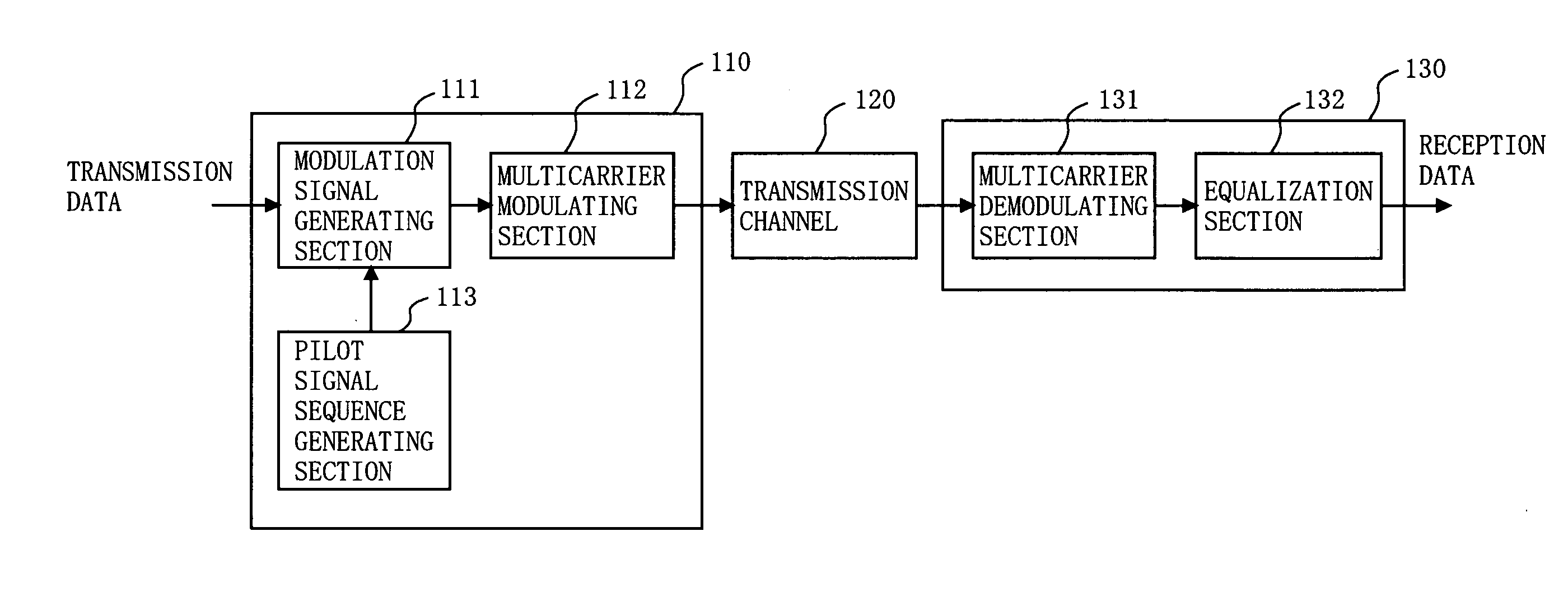
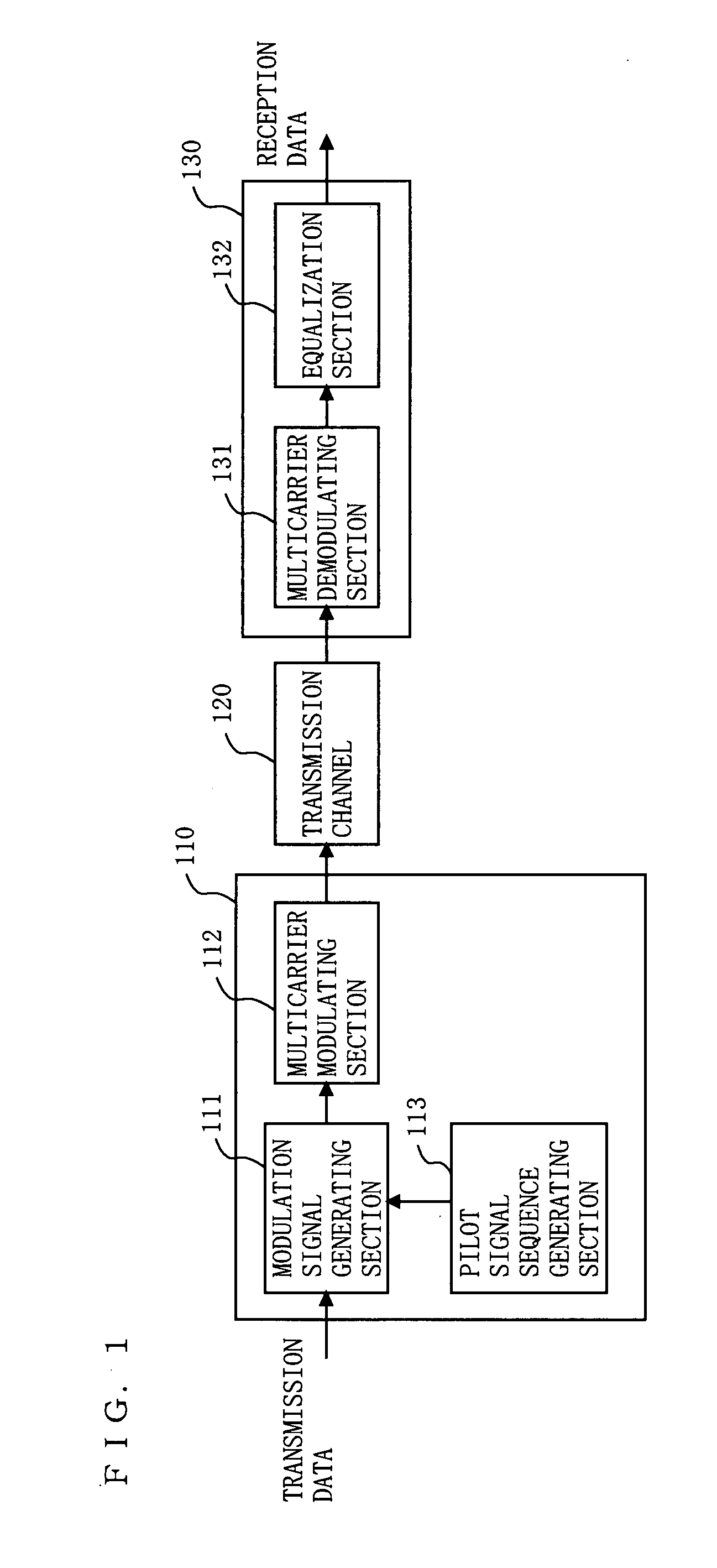
[0082]FIG. 1 is a diagram illustrating a configuration of a communication system employing multicarrier modulation according to a first embodiment of the present invention. In the communication system of FIG. 1, a transmitter 110 and a receiver 130 are connected to each other via a transmission channel 120. A multicarrier signal emitted by the transmitter 110 is received by the receiver 130 via the transmission channel 120. The transmission channel 120 is a wired channel or a wireless channel. When the transmission channel 120 is a wireless channel, transmission from the transmitter 110 to the transmission channel 120 and from the transmission channel 120 to the receiver 130 is performed via an antenna (not shown).

[0083]The transmitter 110 includes a pilot signal sequence generating section 113, a modulation signal generating section 111, and a multicarrier modulating section 112. The pilot signal sequence generating section 113 generates a cyclic pilot signal sequence using a refer...

second embodiment

[0117]FIG. 13 is a diagram illustrating a portion of a frame format in a multicarrier modulation scheme according to a second embodiment of the present invention. In FIG. 13, the horizontal axis represents an arrangement of subcarriers in the frequency direction, and the vertical axis represents an arrangement of symbols in the time direction. Thus, in the multicarrier modulation of the second embodiment, an OFDM / OQAM multicarrier modulation signal is used in which a cycle of reference pilot signal sequence is inserted in a predetermined subcarrier.

[0118]As can be seen from the description of FIG. 7, if a cycle (i.e., four symbols) of reference pilot signal sequence is inserted as a pilot signal, the distance between demodulation vectors of second and third symbols in the reference pilot signal sequence can be maximized without depending on data transmission signals overlapping before and after the pilot signal. Therefore, a transmission channel can be estimated based on the demodul...


PUM


Abstract

In a transmitter, at least one pilot carrier which is modulated with a signal sequence including a reference pilot signal sequence represented by any of amplitude modulation vectors {α, α, −α, −α}, {α, −α, −α, α}, {−α, α, α, −α}, and {−α, −α, α, α} where α represents a real number other than 0, is generated, and an OFDM / OQAM multicarrier modulation signal is transmitted. In a receiver, the OFDM / OQAM multicarrier modulation signal is demodulated, and transmission channel characteristics are estimated and corrected based on two successive demodulation vectors in a time direction which are obtained by demodulating the pilot carrier.

Description

BACKGROUND OF THE INVENTION[0001]1. Field of the Invention[0002]The present invention relates to a method for estimating transmission channel characteristics using a pilot signal, and more particularly, to an estimation method suitable for a multicarrier modulation scheme.[0003]2. Description of the Background Art[0004]In wireless or wired communications, multicarrier modulation is widely used. The multicarrier modulation scheme is a method for dividing and assigning transmission data to a plurality of carriers and modulating and multiplexing the carriers with the respective assigned pieces of the transmission data. OFDM (Orthogonal Frequency Division Multiplexing), which is a type of multicarrier modulation scheme, is widely in practical use in fields, such as digital terrestrial television broadcasting, wireless LAN (Local Area Network), xDSL (x Digital Subscriber Line), PLC (Power Line Communications), and the like. Examples of specific applications include DVB-T for digital terr...

Claims


Application Information

Patent Timeline
IPC IPC(8): H04L27/28
CPCH04L5/0007H04L27/2698H04L25/0224H04L5/0048
Inventor OMOTO, YUKIHIROMORI, KENICHIKIMURA, TOMOHIRO
Owner REDWOOD TECHNOLOGIES LLC
Learn More