Display panel and method for fabricating the same

a technology for a display panel and a manufacturing method, which is applied in the manufacture of electrode systems, instruments, electric discharge tubes/lamps, etc., can solve the problems of lowering mechanical strength, glass substrate breaking, and no publication discloses the use of layered products or composites, so as to reduce the quantity of heat appliable in the fabrication process and reduce the accuracy of alignmen

Inactive Publication Date: 2008-07-03
SHARP KK
View PDF12 Cites 11 Cited by
  • Summary
  • Abstract
  • Description
  • Claims
  • Application Information

AI Technical Summary

Benefits of technology

[0012]In this display panel, the mechanical strength of the display panel is improved by covering merely the outer face of the one or two glass substrates with the resin. This is because sufficient strength against external stress can be secured by reinforcing merely the outermost face of the display panel with the resin since the opposing two glass substrates are bonded to each other with the sealing material. Accordingly, as compared with the case where the both faces of the respective two glass substrates are reinforced, the total thickness of the resin layer is smaller in this display panel, and hence, a small thickness and a small weight of the display panel can be realized. Also, since this display panel has mechanical strength sufficient for resisting impact applied on a fabrication line, the display panel is suitable for mass production using the fabrication line.
[0034]The step of forming a resin layer preferably includes a sub-step of covering end faces and outer faces of the pair of glass substrates with the resin layer. In this fabrication method, the step of aligning substrates is performed before forming the resin layer on the end faces and the outer faces of the pair of glass substrates, in other words, the whole outer face of the display panel. Therefore, the restriction in the quantity of heat appliable in the fabrication process can be relaxed. Furthermore, in obtaining a layered plate by providing the resin layer on the glass substrate or in process for applying heat to the layered plate such as pressing process, the layered plate can be prevented from having a warp due to a difference in the coefficient of thermal expansion between the glass and the resin (for example, a plastic). Moreover, the problem such as lowering of alignment accuracy can be avoided in the step of aligning the substrates. Accordingly, a thin resin (for example, a plastic film) tempered glass substrate can be easily obtained.

Problems solved by technology

When a glass substrate with a thickness smaller than 0.4 mm is used, the mechanical strength is lowered, and hence, there arises, for example, a problem that the glass substrate is broken during the use.
None of the aforementioned publications discloses use of the layered product or the composite described therein as a substrate for a display device.
First, in order that a liquid crystal panel resists impact applied on the fabrication line, both faces of a glass substrate should be coated with a resin. Accordingly, the total thickness of the layered product or the composite is increased, and hence, it is difficult to reduce the thickness and the weight of a display device. In addition, the fabrication cost is increased.
Secondly, since the heat resistance temperature is varied (approximately between 250° C. through 300° C.) depending upon the kind of resin to be employed, the quantity of heat appliable to the layered product or the composite during the fabrication process is restricted. Also, in placing a resin layer on a glass substrate and in heating / cooling process for the layered plate, a warp is caused in the layered product or the composite due to the difference in the coefficient of thermal expansion between the glass and the resin, and hence, the ratio of defectives is high. For example, in the case where a layered substrate in which a resin layer is provided on a glass substrate with a thickness of approximately 0.2 mm is allowed to pass through the fabrication line, when the heating / cooling process is repeated, a warp is caused in the substrate due to the difference in the coefficient of thermal expansion between the glass and the resin even at a temperature lower than the heat resistance temperature of the resin. As a result, a problem may occur that the substrate is broken or the patterning accuracy or the aligning accuracy is lowered. Accordingly, due to these restrictions on the fabrication line, the layered product and the composite disclosed in the aforementioned publications cannot be suitably used for mass production of liquid crystal panels.
In this substrate for a display device, however, since the resin layers are formed on the faces of the glass layer, when a pair of these substrates for a display device are used for fabricating a liquid crystal panel, the thickness of the liquid crystal panel is large.
Thus, it is difficult to reduce the thickness and the weight of the display panel.

Method used


Image

  • Display panel and method for fabricating the same
  • Display panel and method for fabricating the same
  • Display panel and method for fabricating the same

Examples


embodiment 1

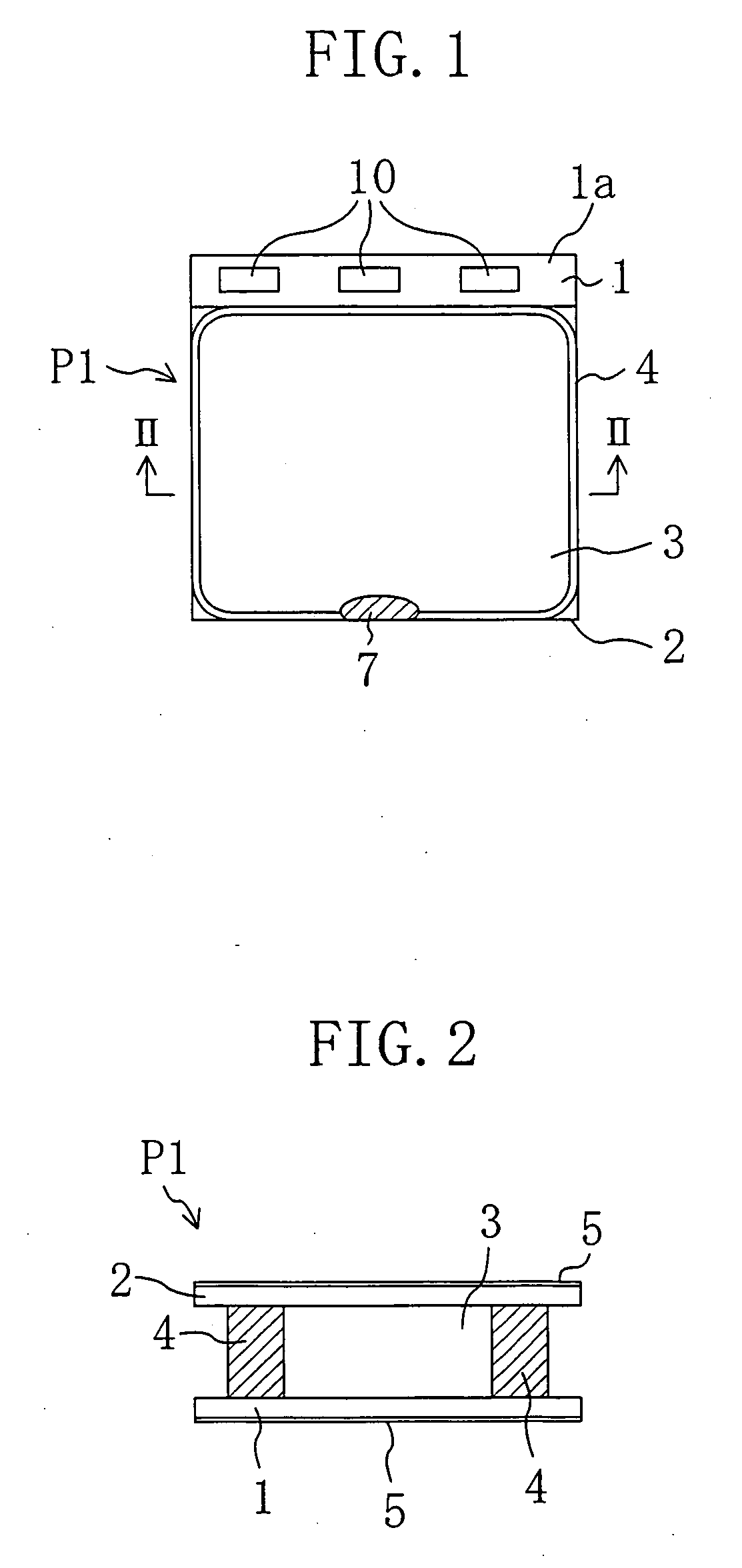
[0057]FIG. 1 is a plan view for schematically showing a liquid crystal panel P1 according to Embodiment 1, and FIG. 2 is a cross-sectional view thereof taken along line II-II of FIG. 1. This liquid crystal panel P1 includes an IC chip for driving a liquid crystal (hereinafter referred to as the “driving IC”) 10 mounted in the form of a bare chip on the liquid crystal panel P1 by the COG (Chip On Glass) method.

[0058]The liquid crystal panel P1 has an element substrate 1 on which a switching element is formed, a counter substrate 2 disposed to oppose the element substrate 1, and a liquid crystal layer 3 interposed between these substrates 1 and 2. The substrates 1 and 2 are aligned with a sealing material 4 sandwiched therebetween. On one face of the element substrate 1 on the side of the liquid crystal layer 3 (namely, the inner face), a plurality of pixel electrodes (not shown) arranged in the form of a matrix are formed, and on one face of the counter substrate 2 on the side of the...

embodiment 2

[0075]FIG. 5 is a cross-sectional view for schematically showing a liquid crystal panel P2 according to Embodiment 2. In the drawings referred to below, the same reference numerals are used to refer to elements with substantially like functions as those of the liquid crystal panel P1, so as to omit the description.

[0076]The liquid crystal panel P2 of this embodiment is different from the liquid crystal panel P1 of Embodiment 1 in a polarizing layer 8 formed on the inner faces of the element substrate 1 and the counter substrate 2. When the polarizing layer 8 is thus formed in the liquid crystal panel P2, polarized light can be prevented from being disturbed by in-plane variation in the substrate thickness caused by etching or variation in the thickness of the resin layer, and hence, the display quality can be prevented from being harmfully affected by disturbed polarized light. Furthermore, since the polarizing layer 8 is formed on the element substrate 1 and the counter substrate 2...

embodiment 3

[0078]FIG. 6 is a plan view for schematically showing a liquid crystal panel P3 according to Embodiment 3, and FIG. 7 is a cross-sectional view thereof taken along line VII-VII of FIG. 6. In the liquid crystal panel P3 of this embodiment, a resin layer 5 is formed on the outer face of an element substrate 1 and the inner face of a terminal portion la of the element substrate 1. In other words, the resin layer 5 is formed on the both faces of the terminal portion 1a. Also, a connection part between a terminal and a driving IC 10 is covered with a resin. Since the connection part between the terminal and the driving IC 10 is reinforced by the resin coat in this manner, the connection reliability can be improved.

[0079]The fabrication process for the liquid crystal panel P3 of this embodiment will now be described with reference to the accompanying drawings. FIGS. 8A and 8B are plan views for schematically showing fabrication procedures for the liquid crystal panel P3, and FIGS. 9A, 9B ...


PUM


Abstract

The display panel of this invention includes a pair of glass substrates each with a thickness not less than 0.15 mm and not more than 0.3 mm and a sealing material for bonding the pair of glass substrates to each other. A resin layer is formed on the outer face of at least one of the pair of glass substrates.

Description

BACKGROUND OF THE INVENTION[0001]The present invention relates to a display panel and a method for fabricating the display panel. The display panel of this invention is applicable to a liquid crystal panel, a plasma display panel, an electrochromic display panel and the like.[0002]In order to reduce the thickness of a liquid crystal panel, that is, one of display devices, reduction in the thickness of a substrate has been conventionally examined. In a current liquid crystal panel, a pair of glass substrates each having a thickness of 3 mm through 0.4 mm are generally used, and a liquid crystal layer with a thickness of several μm is interposed between these substrates. When a glass substrate with a thickness smaller than 0.4 mm is used, the mechanical strength is lowered, and hence, there arises, for example, a problem that the glass substrate is broken during the use.[0003]Japanese Laid-Open Patent Publication No. 6-340029 discloses a layered plate in which a glass film with a thic...

Claims


Application Information

Patent Timeline
Patent Type & Authority Applications(United States)
IPC IPC(8): H01J9/26G02F1/1339G02F1/1333H01L51/52
CPCH01L51/5237G02F1/133305H10K50/844H10K50/8426G02F1/1339
Inventor OTA, YOSHIFUMIYOSHIMIZU, TOSHIYUKI
Owner SHARP KK
Why Eureka
Try Eureka