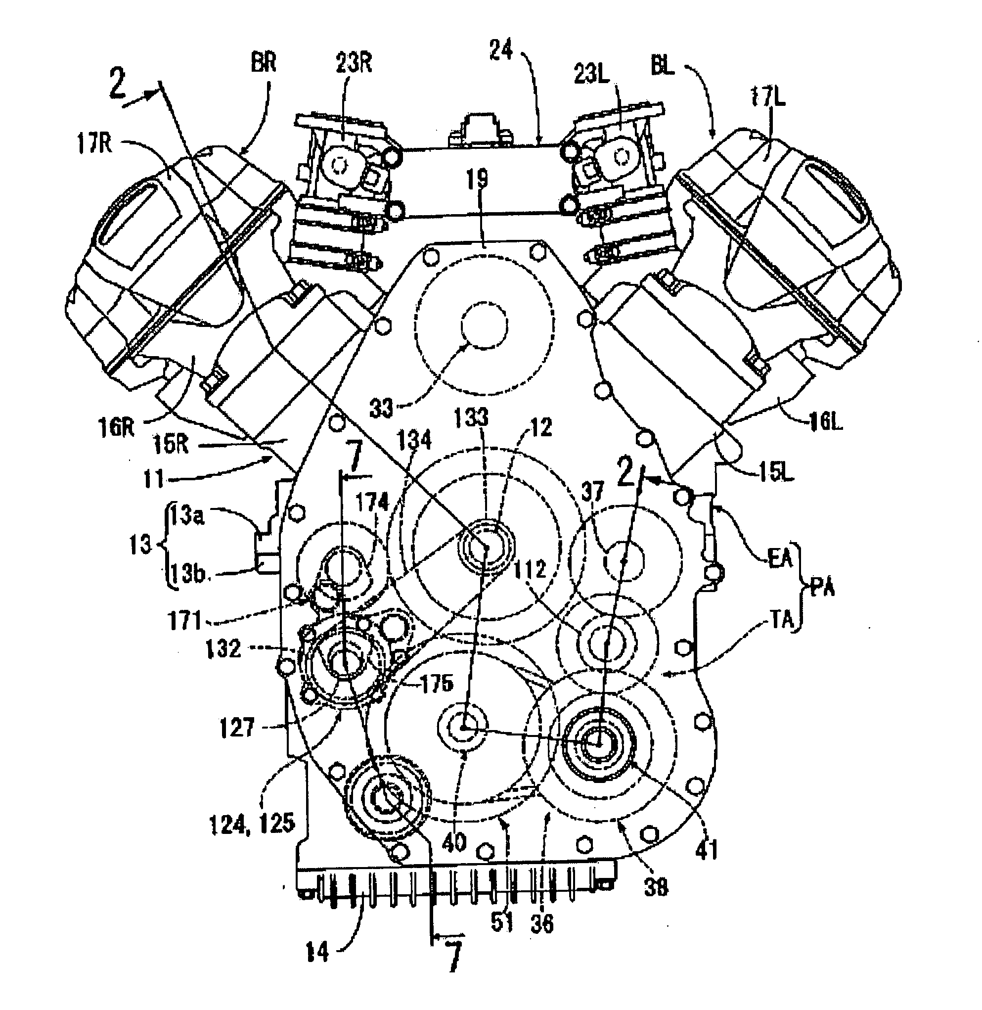
Power unit for motorcycle
a technology for power units and motorcycles, applied in machines/engines, transportation and packaging, gearing, etc., can solve the problems of more complex configuration of oil passages, and achieve the effect of reducing the number of necessary oil passages, simple structure of oil passages, and preventing the charge of starter systems when internal combustion engines are started
- Summary
- Abstract
- Description
- Claims
- Application Information
AI Technical Summary
Benefits of technology
Problems solved by technology
Method used
Image
Examples
first embodiment
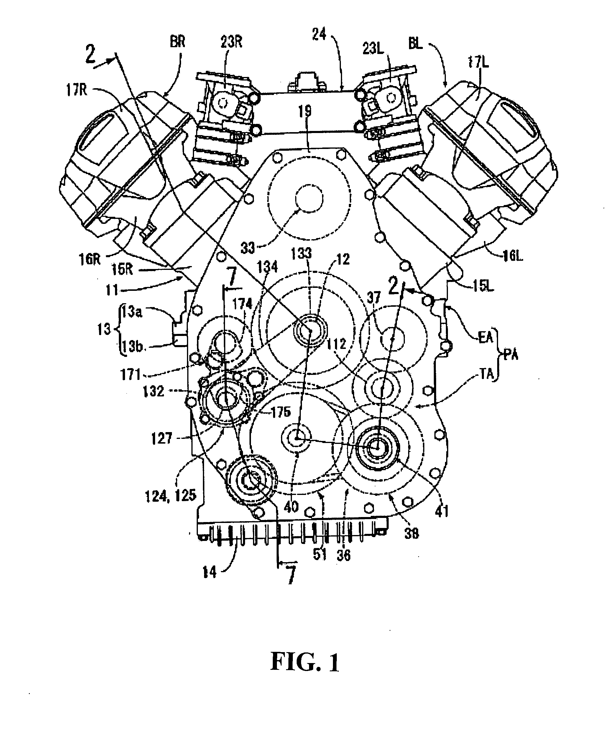
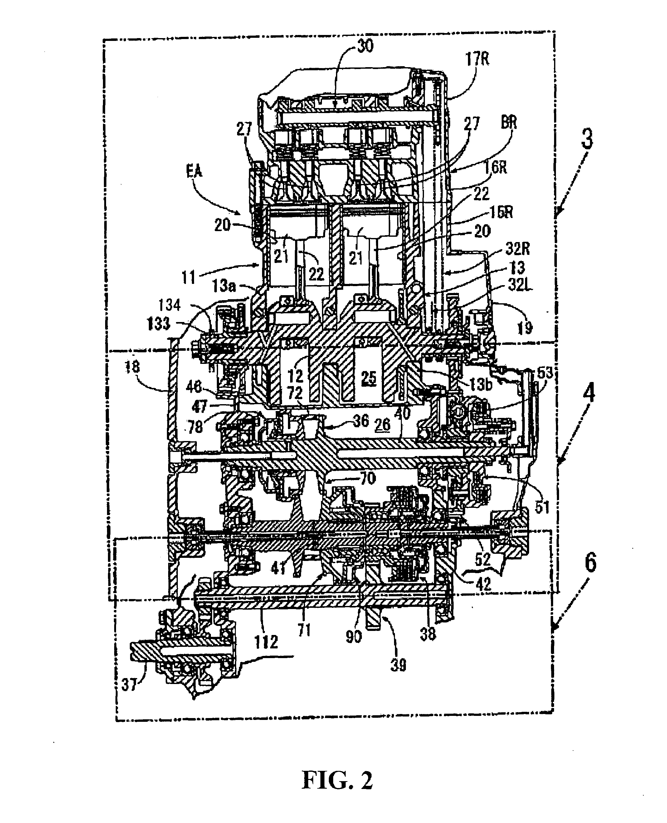
[0083]Now, descriptions will be given as to some advantageous effects of the The input clutch is provided on the drive pulley shaft 40 as being set between the crankshaft 12 and the drive pulley shaft 40 while the starter clutch 38 is provided on the driven pulley shaft 41 as being set between the driven pulley shaft 41 and the rear wheel. Consequently, when the internal combustion engine EA starts, the power transmission to the continuously-variable-transmission 36 side can be discontinued. The load on the starter system at the time of starting the internal combustion engine EA can be reduced, and thus the starter system can be made smaller in dimension. In addition, even with a disconnection of the starter clutch 38 that occurs at the time of stopping the internal combustion engine EA, the torque from the crankshaft 12 can be transmitted to the continuously variable transmission 36 via the input clutch 51. Thus, the continuously variable transmission 36 can be shifted from a high...
second embodiment
[0090]FIG. 8 shows the present invention. An input clutch 51′ switches between the connection of and the disconnection of the transmission of drive power from the crankshaft 12 to the drive pulley shaft 40 via the primary reduction-gear mechanism 52. The switching between the engagement and the disengagement of the input clutch 51′ is controlled hydraulically, and the input clutch 51′ is housed in a transmission chamber 26′. A starter clutch 38′, on the other hand, is provided on the driven pulley shaft 41 and is set between the driven pulley 41 and the rear wheel. The switching between the engagement and the disengagement of the starter clutch 38′ is controlled mechanically, and the starter clutch 38′ is housed outside of the transmission chamber 26′.
[0091]In addition, the input clutch 51′ is housed in the transmission chamber 26′ and is provided on the drive pulley shaft 40, while the driven-side hydraulic drive mechanism 90 is annexed to the driven pulley 71 provided on the drive...
third embodiment
[0093]FIGS. 9 and 10 show the present invention.
[0094]Note that the component parts that respectively correspond to those in the first and the second embodiments are given the same reference numerals as those in the first and the second embodiments, and no detail descriptions of those parts will be given here.
[0095]In FIG. 9, a head pipe 190 is provided at the front end of a body frame F of the motorcycle steerably supports the front fork 191, which pivotally supports a front wheel WF. Between the front wheel WF and a rear wheel WR, a power unit PB is mounted on the body frame F. The power unit PB is composed of, for example, a V-type four-cylinder internal combustion engine EB and of a power transmission system TB. The power transmission system TB transmits the power from the internal combustion engine EB to the drive wheel, that is, the rear wheel WR, while reducing the speed of the transmitted power.
[0096]An engine body 192 of the internal combustion engine EB includes a crankcas...
PUM
 Abstract
Description
Claims
Application Information
 - R&D
- Intellectual Property
- Life Sciences
- Materials
- Tech Scout
- Unparalleled Data Quality
- Higher Quality Content
- 60% Fewer Hallucinations
Browse by: Latest US Patents, China's latest patents, Technical Efficacy Thesaurus, Application Domain, Technology Topic, Popular Technical Reports.
© 2025 PatSnap. All rights reserved.Legal|Privacy policy|Modern Slavery Act Transparency Statement|Sitemap|About US| Contact US: help@patsnap.com


