Method of and apparatus for conveying molten metals while providing heat thereto

a technology of conveying apparatus and molten metals, which is applied in the direction of casting apparatus, chemical/physical processes, domestic heating, etc., can solve the problems of slow flow of molten metal through the trough, increased risk of metal solidification (or undue cooling) in the trough, and accelerated oxidation of metal at the surface, so as to prevent oxidation and increase heat conductivity

Inactive Publication Date: 2008-07-10
NOVELIS INC
View PDF20 Cites 40 Cited by
  • Summary
  • Abstract
  • Description
  • Claims
  • Application Information

AI Technical Summary

Benefits of technology

[0019]It has been found that heat-conductive refractories containing silicon carbide are particularly preferred, sometimes protected with a layer of silica to prevent oxidation at high temperatures. Although silicon carbide may be used in its pure form, it is generally mixed in granular form with binders and other refractory compounds in water, cast, dried and cured to form a dense solid. The larger the proportion of silicon carbide, the higher is the heat conductivity of the resulting refractory.

Problems solved by technology

Additionally, molten metal is sometimes filtered through ceramic foam filters to remove solid particles, and the use of such filters may slow the flow of molten metal through a trough.
Consequently, in applications such as these and others, the risk of metal solidification (or undue cooling) in the trough is increased.
Metal in the trough can be heated by directing a flame onto the upper surface of the metal as it flows through the trough, but this has the disadvantage that oxidation of the metal at the surface is thereby accelerated, particularly if the metal is aluminum or an aluminum alloy.
Heating of the trough can be carried out by providing electrical heaters on or adjacent to the inner surface of the trough, but generally such heaters are slow to transfer heat to the metal and are therefore not always very effective in applications of this kind.

Method used


Image

  • Method of and apparatus for conveying molten metals while providing heat thereto
  • Method of and apparatus for conveying molten metals while providing heat thereto
  • Method of and apparatus for conveying molten metals while providing heat thereto

Examples


Embodiment Construction

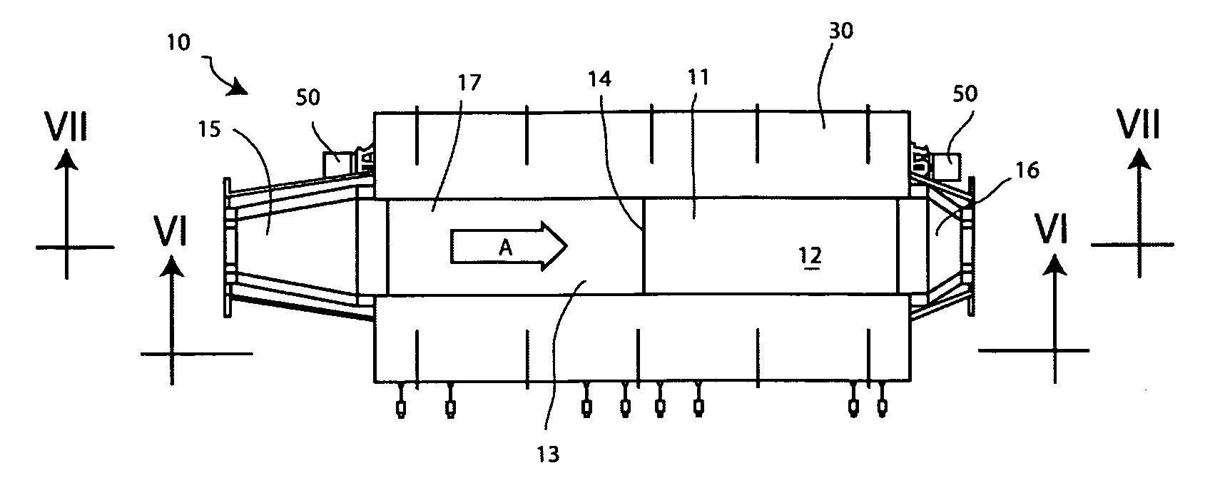
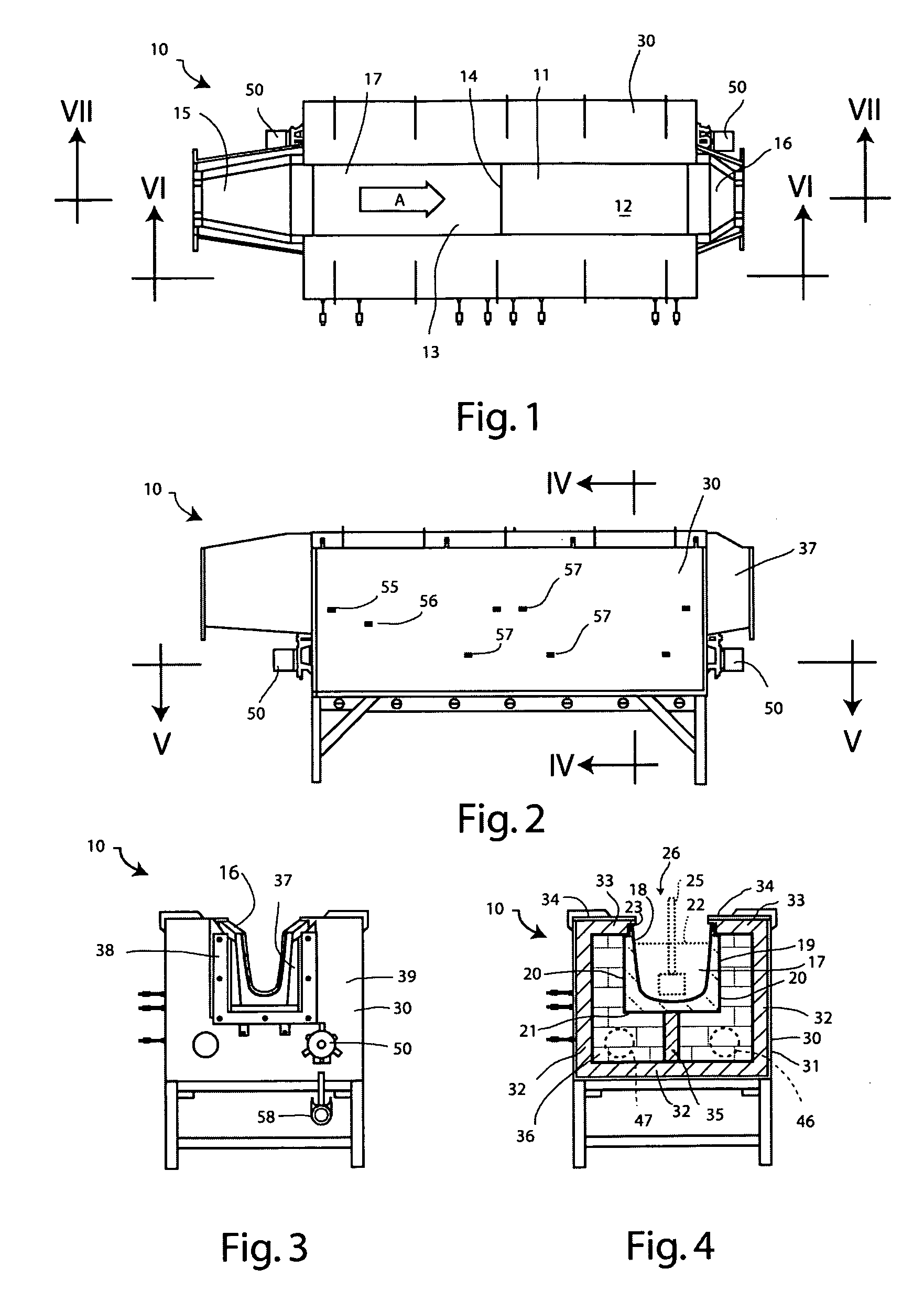
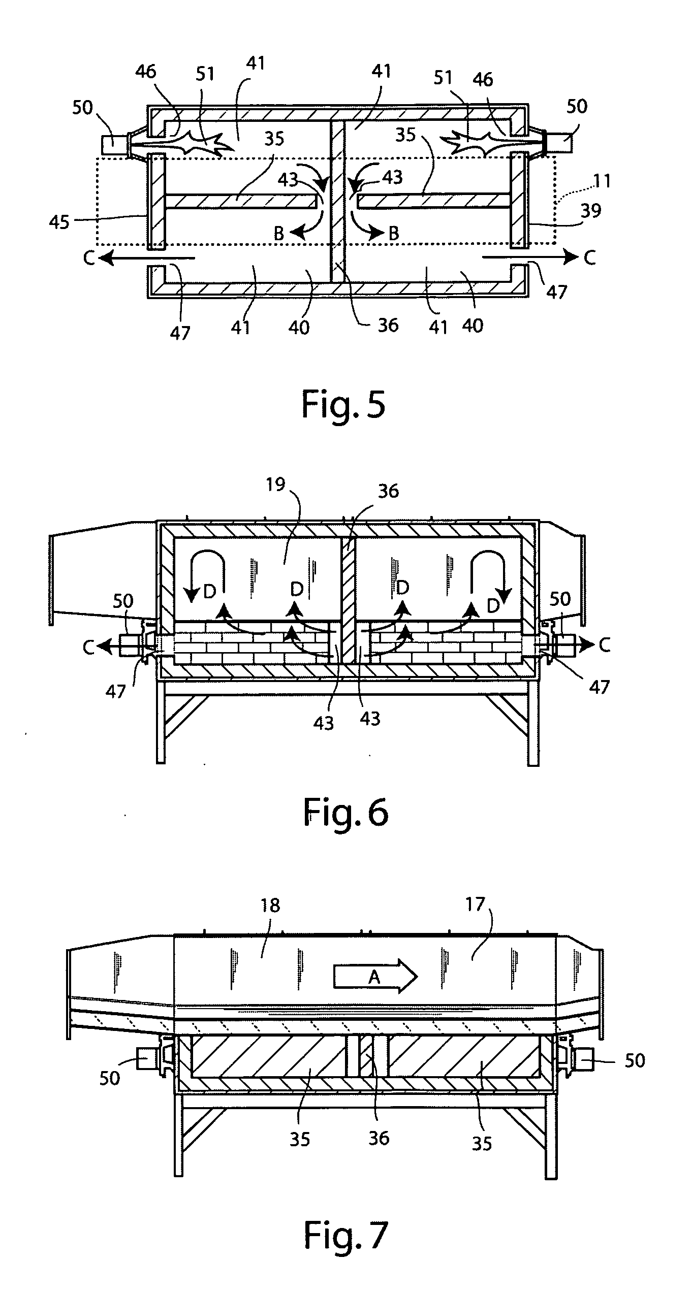
[0031]A first exemplary embodiment of a molten metal conveying apparatus is shown in FIGS. 1 to 7 of the accompanying drawings. This particular embodiment is intended for use with metal degasser nozzles intended for use with molten aluminum or aluminum alloys, thereby forming a compact in-line metal degasser unit which may, for example, be incorporated into a conventional trough or launder leading from a metal melting furnace to a casting apparatus. Other exemplary embodiments may be intended for use with other molten metals.

[0032]The apparatus is indicated generally by reference numeral 10 and includes a section 11 of metal-conveying trough made up of two trough parts 12 and 13 abutting each other at a junction 14. The trough section 11 acts as an elongated channel-forming element that conveys molten metal through the apparatus. Butting up to the trough section 11 at an upstream end is a trough inlet member 15, and butting up to the trough section 11 at a downstream end is a trough...


PUM

PropertyMeasurementUnit
thicknessesaaaaaaaaaa

Abstract

The invention relates to a method of and apparatus for providing heat to a molten metal flowing through metal-conveying apparatus. The apparatus includes a molten metal-conveying channel, an enclosure for receiving and circulating combustion gases while preventing entry of the gases into said channel, a heat-conductive body of material separating at least part of the channel from the enclosure; and a combustion device for generating combustion gases and delivering the gases to the enclosure. Heat from the combustion gases is used to heat molten metal held in the channel, while preventing contact between the combustion gases and the molten metal. The body of material may be a trough used to form the channel, a tube for conveying the molten metal, or a tube acting as the enclosure, or the like.

Description

CROSS-REFERENCE TO RELATED APPLICATIONS[0001]This application claims the priority right of provisional U.S. patent application Ser. No. 60 / 876,045 filed Dec. 19, 2006 by applicants named herein.BACKGROUND OF THE INVENTION[0002]I. Field of the Invention[0003]This invention relates to apparatus used for conveying molten metals during casting operations and the like. More particularly, the invention relates to apparatus for and methods of providing heat to molten metals conveyed in such apparatus to prevent metal freeze-up, undue cooling, or similar effects, during the passage through such apparatus.[0004]II. Background Art[0005]It is common practice during metal casting operations to cause a molten metal to flow through an elongated trough (sometimes called a launder), for example from a melting furnace to a casting mold. Such troughs are made of a material that can resist exposure to the molten metal for a reasonable period of time without undue damage, and the conditions must be suc...

Claims


Application Information

Patent Timeline
Patent Type & Authority Applications(United States)
IPC IPC(8): B22D35/06F24D5/02
CPCB22D35/06C04B35/565C04B35/66C04B2235/3217C04B2235/9676C04B2235/3463C04B2235/77C04B2235/9607C04B2235/3418B01J19/02C04B35/58
Inventor HYMAS, JASON D.REEVES, ERIC W.BRUSKI, RICHARD SCOTT
Owner NOVELIS INC
Why Eureka
Try Eureka