Flame arrester

a technology of flame arrester and flame path, which is applied in the field of flame arrester, can solve the problems of ineffective flame arrester and inability to function, and achieve the effect of increasing the flow resistance and increasing the length of the flame path

Inactive Publication Date: 2008-07-10
READE CHARLES OSBORN
View PDF9 Cites 4 Cited by
  • Summary
  • Abstract
  • Description
  • Claims
  • Application Information

AI Technical Summary

Benefits of technology

[0013]Most flame arresters have a continuous open path where the flame only needs to move in one direction. Such passages laminate a flow of gas causing an explosion to be starved of air. This is beneficial, but at the same time increases flow resistance. It is also possible to look through these flame arresters and high velocity explosions will therefore often pass through them for this reason. Flame arresters according to the present invention are therefore preferably designed so that rods in parallel rows are offset with respect to the adjacent row. This makes it necessary for a gas or explosion front to weave in order to pass through the labyrinth. This weaving action and the fact that the gas must follow a path at an angle to the normal axis means that the length of the flame path is increased, making this a more effective flame arrester. Suitable offset angles can vary. Examples are between 30 and 60 degrees, but this is not exhaustive. The continuous weaving action also causes the gas to accelerate and decelerate which causes a small amount of turbulence.
[0014]An additional principal advantage of a rod type flame arrester is that it lends itself to being cleaned mechanically, simply by introducing a linear scraping device. This preferably passes over each rod to keep it clean. The scraping device can either be operated by manual effort or automatically.

Problems solved by technology

Most known flame arresters cannot function if their temperature exceeds 100° C. and none are effective above 200° C. Conventional flame arresters are not therefore effective if a hot air flow is involved.

Method used


Image

  • Flame arrester
  • Flame arrester
  • Flame arrester

Examples


first embodiment

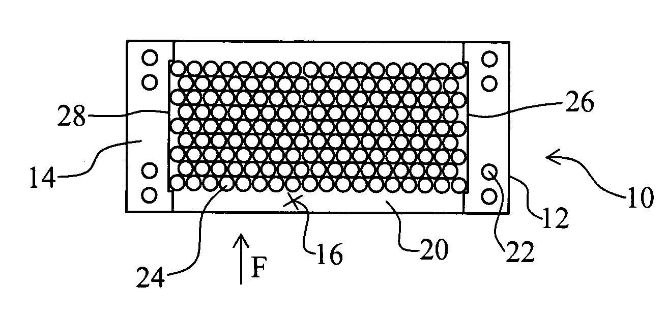
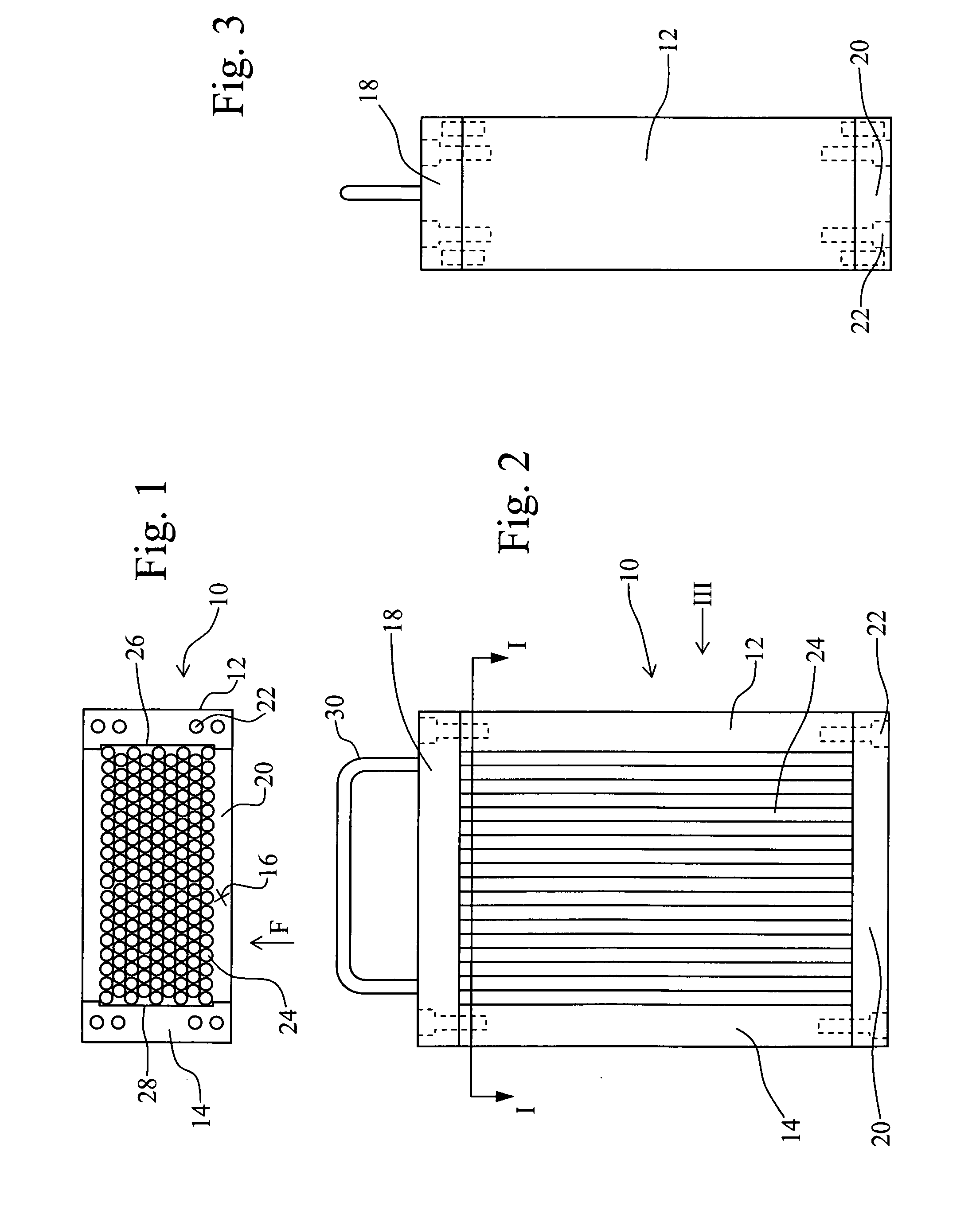
[0025]FIGS. 1, 2 and 3 illustrate the present invention. A flame arrester 10 comprises a pair of side walls 12, 14 which are generally parallel and define between them a flow passage 16 through which air flows in direction F. The top and bottom edges of the flow passage 16 are defined by upper and lower walls 18 and 20. These are secured to the side walls 12, 14 by bolts such as that marked at 22.

[0026]An array of parallel circular section rods 24 are provided within the flow passage 16. They are assembled transverse to the flow direction F in a hexagonal pattern such that rods in one row are offset with respect to rods in an adjacent row. Thus, the only route through the flow passage 16 is in the interstices between rods 24, a path which must deviate from a straight line parallel to the passage walls at some point. The rods 24 are generally close packed, insufficiently so as to close off air flow through the passage 16, but sufficiently close as to require significant deviation. As...

second embodiment

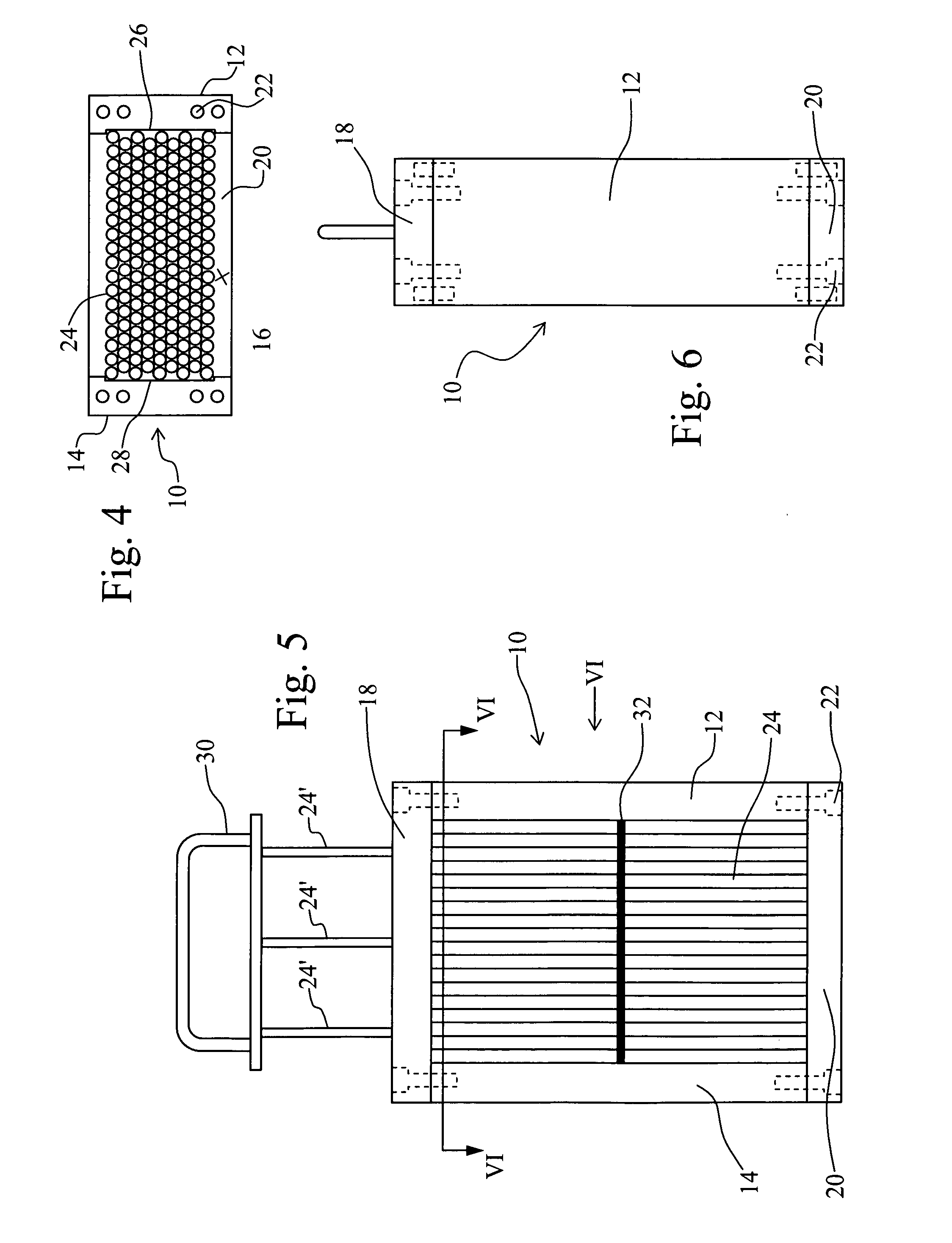
[0030]FIGS. 4, 5 and 6 illustrate a In general, this embodiment is identical to that described above with reference to FIGS. 1, 2 and 3. Identical reference numerals are therefore employed to denote corresponding parts.

[0031]In this second embodiment, a scraper plate 32 is provided within the array of rods 24. This scraper plate 32 includes an array of circular section apertures corresponding to the circular section rods 24. It can therefore exist within the array of rods 24. A plurality of rods 24′ are fixed at their bottom end to the scraper plate 32 and at their top end to the handle 30, passing through apertures in the upper wall 18. Thus, when the handle 30 is pulled upwardly, the scraper plate 32 is drawn through the array of rods 24, scraping deposits from the surfaces thereof as it passes. After the handle 30 has been pulled to it fullest extent and the scraper plate 32 is adjacent the undersurface of the top wall 18, the handle 30 can be depressed, moving the scraper plate...

third embodiment

[0033]the invention is shown in FIGS. 7 and 8. In this embodiment, the pair of side walls and upper and lower walls is replaced with a tube 50. This assembly would be suited to pipe line applications, the hoop giving added strength where high pressure detonations may occur. The flow path is therefore within the tube 50, an array of parallel circular rods 52 of varying length being provided within the flow path, although square or polygonal rods can be used. The rods 52 are assembled transverse to the flow direction F in a pattern where alternate rows of rods 52 are aligned and rows between these are offset by one half of the rod pitch. Thus, the only route through the flow passage is in the interstices between the rods 52, a path which must deviate from a straight line parallel to the surrounding hoop 50 at some point.

[0034]The rods 52 are generally close packed, insufficiently so as to close off air flow but sufficiently close as to require significant deviation. Where the vertical...


PUM


Abstract

The flame arrester comprises a flow passage in which are disposed a plurality of generally aligned rods such that fluids flowing in the passage must pass between the rods. Rows of rods are used to construct the flame arrester element, ideally closely spaced and these present a natural surface over which air can flow with minimal flow resistance. The rods can be of any size and the gaps between them can be selected to arrest explosions due to different gases or vapours in air. The rod diameter can be altered to withstand different levels of explosion pressure, making it possible to construct both deflagration and detonation flame arresters. If tubes are used these can carry cooling fluid making the arrester more effective at coping with continuous burning. Rods in parallel rows can be offset with respect to the adjacent row. Suitable offset angles can vary.

Description

TECHNICAL FIELD OF THE INVENTION[0001]The present invention relates to flame arresters.BACKGROUND ART[0002]Flame arresters are used either to halt an internal explosion so that it will not ignite a surrounding explosive atmosphere, or to prevent an external fire or explosion from igniting an internal explosive atmosphere that must be handled with safety within a system.[0003]In the majority of cases it is necessary for a flow of air to pass through plant or machinery. Some plant or machinery has internal sources of ignition, and internal explosions can occur if a gas or vapour becomes entrained in the flow. In some cases there is a risk of gases or vapours in potentially explosive concentrations being ingested from outside. In other cases, where flammable materials are being pumped for example under vacuum, it is possible for a potentially explosive atmosphere to be present as part of a process. To prevent the escape of internal explosions in these applications, flame arresters are ...

Claims


Application Information

Patent Timeline
Patent Type & Authority Applications(United States)
IPC IPC(8): A62C2/00A62C4/00A62C4/02G08B17/00
CPCA62C4/02
Inventor READE, CHARLES OSBORN
Owner READE CHARLES OSBORN
Why Eureka
Try Eureka