Noncontact power-transmission coil, portable terminal and terminal charging device, planar coil magnetic layer formation device, and magnetic layer formation method

a technology of power-transmission coil and charging device, which is applied in the direction of magnets, inductances, magnetic bodies, etc., can solve the problems of insufficient adhesion properties of planar coil and magnetic sheet, and achieve the effects of improving power-transmission efficiency, reducing the thickness of portable terminal and terminal charging device, and increasing linked magnetic flux

Active Publication Date: 2008-07-10
SONY MOBILE COMM INC +1
View PDF8 Cites 121 Cited by
  • Summary
  • Abstract
  • Description
  • Claims
  • Application Information

AI Technical Summary

Benefits of technology

[0021]That is, according to the embodiments of this invention, by applying a magnetic layer so as to cover one planar portion and a side-face portion of the planar coil, a magnetic path can be formed efficiently, and moreover linked magnetic flux can be increased.
[0022]According to the embodiments of the invention, by applying a magnetic layer so as to cover one planar portion and the side-face portion of the planar coil, a noncontact power-transmission coil can be made even thinner and power-transmission efficiency can be improved, and moreover a portable terminal and terminal charging device can also be made thinner.

Problems solved by technology

That is, because depressions and protrusions are formed in the planar portion of the planar coil by the windings of electric wire 201, if a thin adhesive sheet, for example, is used, the adhesive properties of the planar coil and the magnetic sheet may not be sufficient, and the magnetic sheet may separate from the planar coil.

Method used


Image

  • Noncontact power-transmission coil, portable terminal and terminal charging device, planar coil magnetic layer formation device, and magnetic layer formation method
  • Noncontact power-transmission coil, portable terminal and terminal charging device, planar coil magnetic layer formation device, and magnetic layer formation method
  • Noncontact power-transmission coil, portable terminal and terminal charging device, planar coil magnetic layer formation device, and magnetic layer formation method

Examples


Embodiment Construction

[0062]Below, embodiments of the invention are explained, referring to the drawings.

[0063]In the embodiments, a mobile phone unit is described as an example of a portable terminal including a noncontact power-transmission coil having a spiral-shape planar coil according to an embodiment of the invention, and a cradle capable of charging at least the above mobile phone unit is described as an example of a terminal charging device according to an embodiment of the invention; of course these explanations are examples, and the invention is not limited to these examples.

[0064][Basic Configuration and Operation During Charging of Cradle and Mobile Phone Unit]

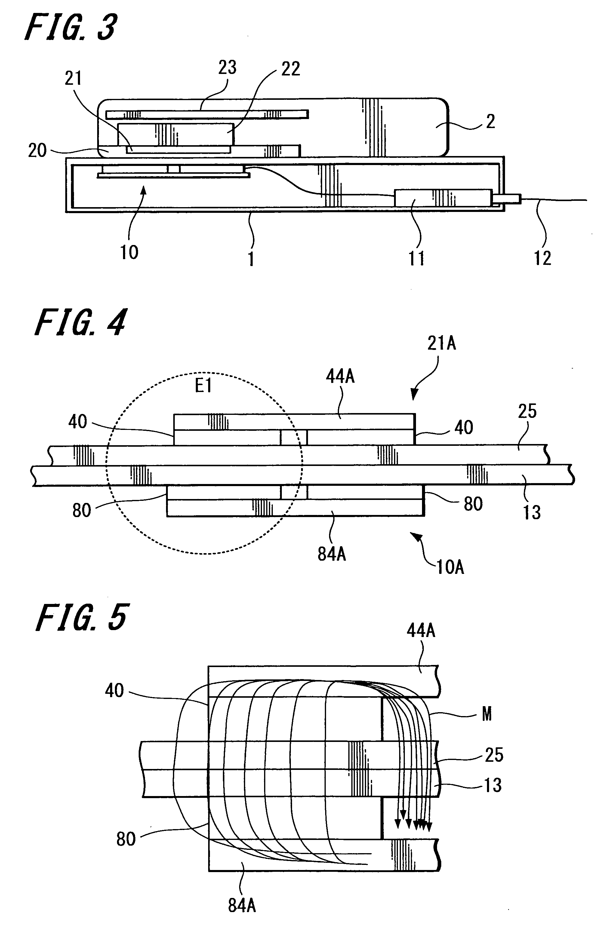
[0065]FIG. 3 is a schematic diagram showing the internal construction of principal portions of a mobile phone unit 2 and a cradle 1 according to an embodiment of the invention.

[0066]The mobile phone unit 2 of this embodiment includes, within a housing thereof, at least a battery 22 having a rechargeable battery which generates the oper...


PUM

PropertyMeasurementUnit
magneticaaaaaaaaaa
flexibleaaaaaaaaaa
poweraaaaaaaaaa

Abstract

A noncontact power-transmission coil is provided. The noncontact power-transmission coil includes a planar coil and a magnetic layer. The planar coil is formed by winding a linear conductor in a spiral shape substantially in a single plane. The magnetic layer is formed by applying a liquid-form magnetic solution in which magnetic particles are mixed with a binder solvent, so as to cover one planar portion of the planar coil and a side-face portion of the planar coil.

Description

CROSS-REFERENCES TO RELATED APPLICATIONS[0001]The present invention contains subject matter related to Japanese Patent Application JP 2007-001642, filed in the Japanese Patent Office on Jan. 9, 2007, the entire contents of which are incorporated herein by reference.BACKGROUND OF THE INVENTION[0002]1. Field of the Invention[0003]This invention relates to a noncontact power-transmission coil for use in power transmission in a noncontact manner using electromagnetic induction, when charging a rechargeable battery incorporated in a small-size, thin portable terminal such as a mobile phone unit. The invention further relates to a portable terminal and terminal charging device incorporating such a noncontact power-transmission coil, and to a magnetic layer formation device and magnetic layer formation method for forming a magnetic layer in a planar coil of such a noncontact power-transmission coil.[0004]2. Description of the Related Art[0005]In the past, systems have been known in which c...

Claims


Application Information

Patent Timeline
Patent Type & Authority Applications(United States)
IPC IPC(8): H01F27/28H02J7/00B05D5/12H01F17/00H01F17/04H01F38/14
CPCH01F5/003H01F27/24H01F27/2871Y10T29/49073H01F41/16H02J7/025Y10T29/53165H01F38/14H02J50/10H02J7/00045H02J50/005H02J50/60
Inventor KATO, HIROSHISUZUKI, KUNIHARUSUZUKI, KATSUYAYAMAZAKI, MANABUKONDO, YOICHIROONISHI, KOTAYODA, KENTAROJIN, MIKIMOTOKAMIJO, TAKAHIROSOGABE, HARUHIKO
Owner SONY MOBILE COMM INC
Why Eureka
Try Eureka