System for protecting bearings and seals of a refrigerant compressor

a technology for refrigerant compressors and seals, which is applied in the direction of positive displacement liquid engines, piston pumps, lighting and heating apparatus, etc., can solve the problems of affecting the performance of the compressor

Active Publication Date: 2008-07-10
TRANE INT INC
View PDF4 Cites 20 Cited by
  • Summary
  • Abstract
  • Description
  • Claims
  • Application Information

AI Technical Summary

Benefits of technology

[0011]It is an object of the invention to protect the bearings, seals, and/or the lubricant of a refrigerant compr

Problems solved by technology

For years, it has been known that adverse shaft voltage can develop between the shaft and housing of electric motors.
When the voltage discharges with sufficient energy across a bearing that supports the shaft, the resulting current can damage the bearing through electrical arcing and/or by degrading the bearing's lubricant.
In cases where the motor is driven by an AFD (adjustable frequency drive) with high speed power switching devices (e.g., insulated gate bipolar transistors), the rapid switching rate of the power switching devices can generate a high frequency common mode voltage that can ultimately lead to a damaging component of the shaft voltage.
Although s

Method used


Image

  • System for protecting bearings and seals of a refrigerant compressor
  • System for protecting bearings and seals of a refrigerant compressor
  • System for protecting bearings and seals of a refrigerant compressor

Examples


Embodiment Construction

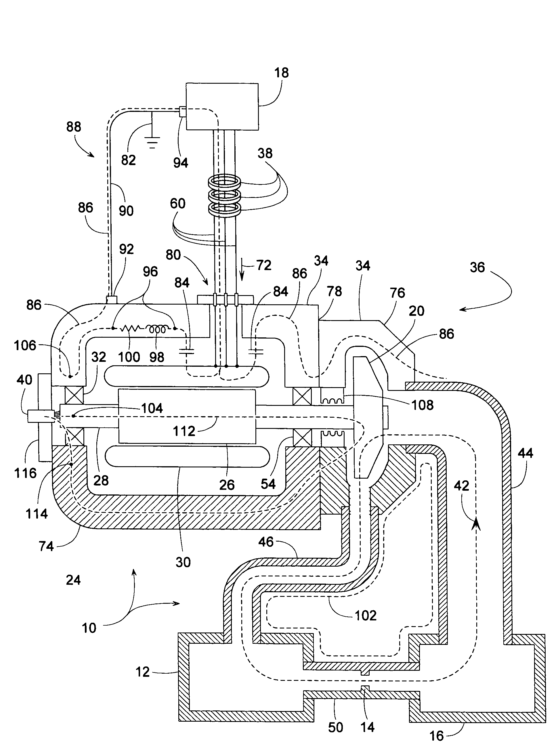
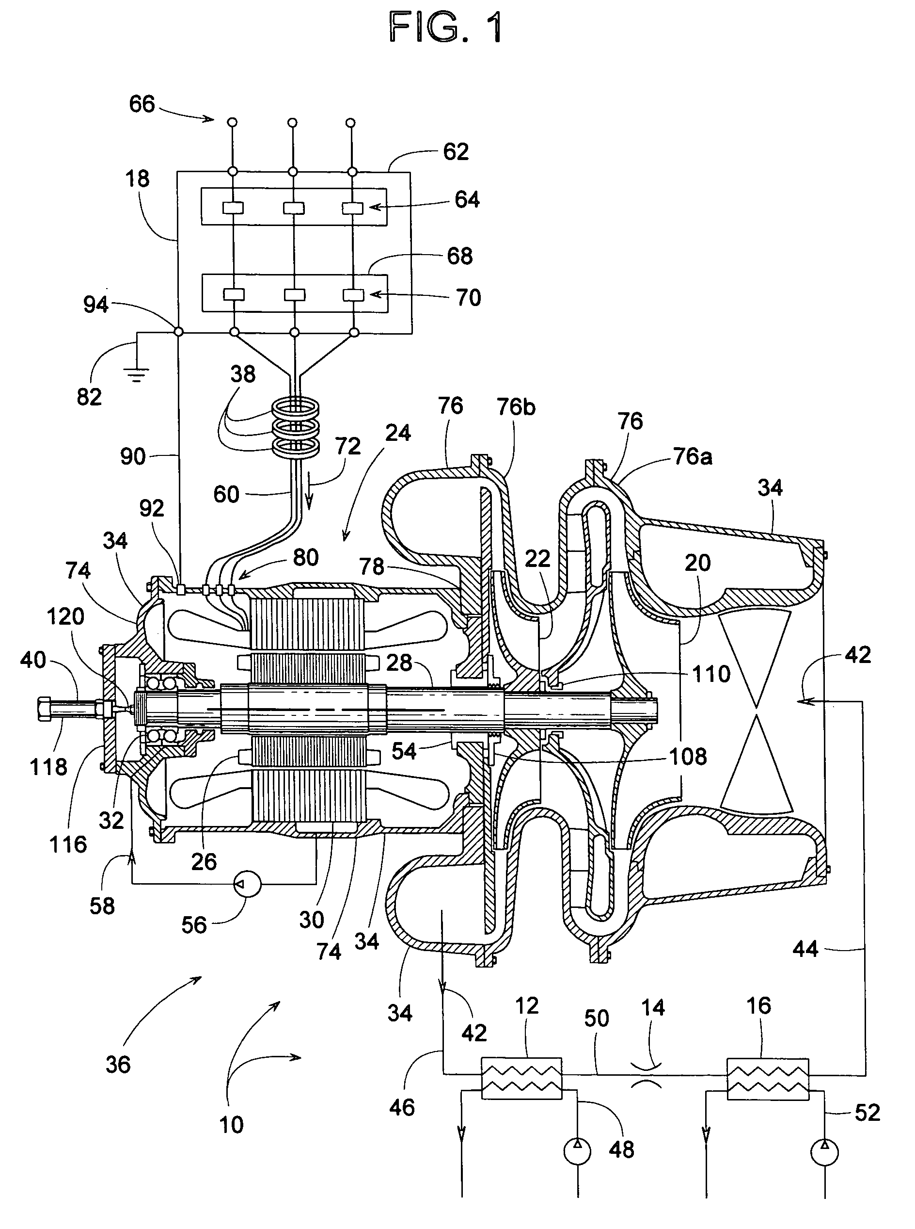
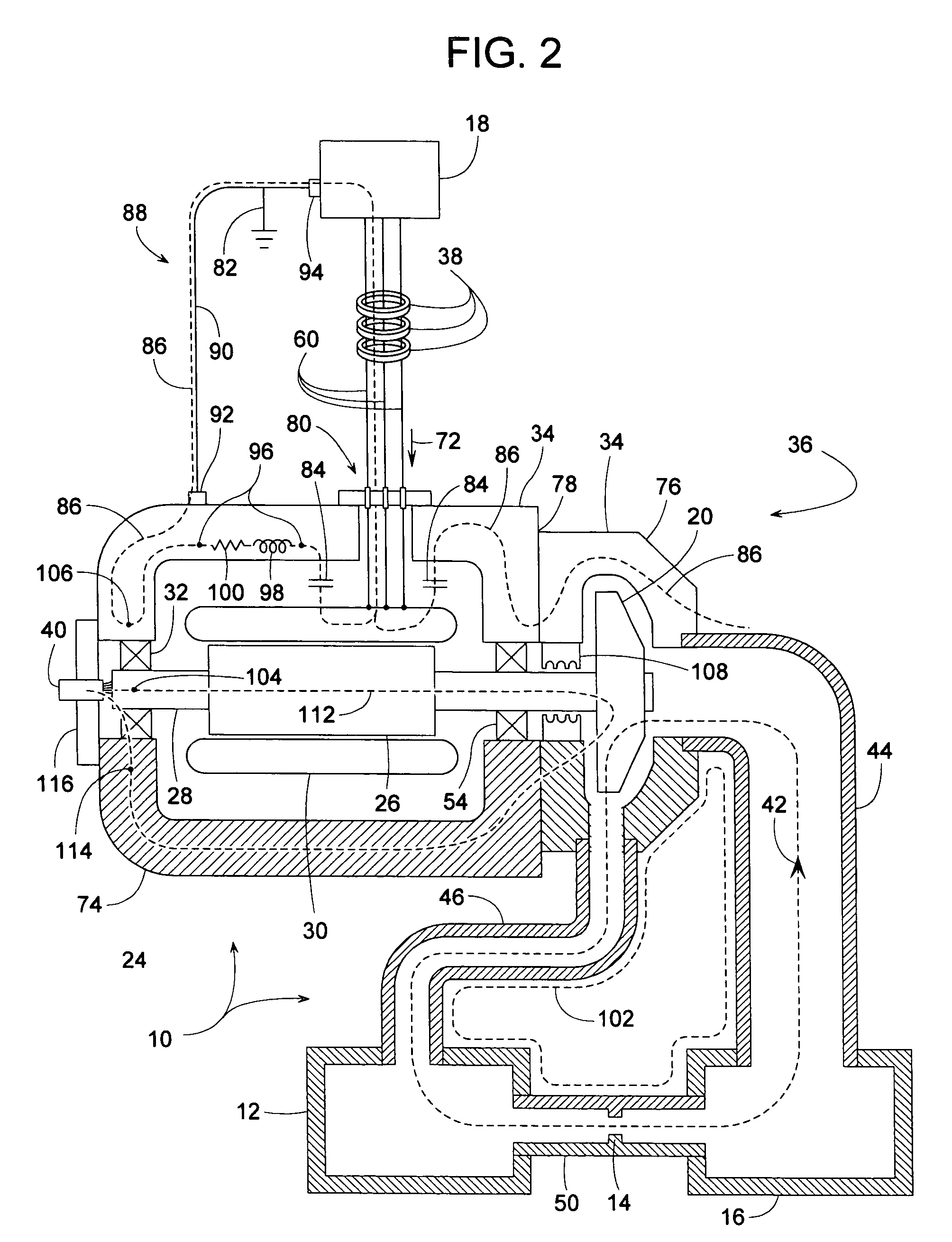
[0037]A refrigerant system 10, shown in FIG. 1, comprises a condenser 12, an expansion device 14, an evaporator 16, and a compressor system 36 driven at varying speed by an AFD 18 (adjustable frequency drive). For the illustrated embodiment, compressor system 10 comprises two centrifugal impellers (a first stage impeller 20 and a second stage impeller 22) driven by a motor 24, wherein motor 24 includes a rotor 26, a shaft 28 extending from rotor 26, stator windings 30, and at least one rolling element bearing 32 that helps support shaft 28 within a cast iron housing 34. Compressor system 36 includes one or more inductors 38 and / or a grounding contact device 40 (typically a brush) to help protect bearing 32 against a composite adverse shaft voltage. The composite adverse shaft voltage and its various components will be explained after a more detailed description of refrigerant system 10 and compressor system 36.

[0038]Refrigerant system 10 contains a refrigerant 42 (e.g., R123, R134a,...


PUM

PropertyMeasurementUnit
Electrical conductivityaaaaaaaaaa
Electrical inductanceaaaaaaaaaa
Ratioaaaaaaaaaa

Abstract

To protect the bearings, lubricant and seals of a refrigerant compressor, the compressor includes one or more inductors for mitigating a high frequency common mode current that produces a high frequency shaft voltage. Each inductor is a ring of magnetic material encircling three insulated cables that convey three-phase power from an adjustable frequency drive to the compressor's motor. Without the inductors, the high frequency shaft voltage can become damagingly high due to the length of a cast iron housing that can be particularly long if the housing contains both a motor and several centrifugal impellers. The high frequency shaft voltage is just one component of a composite adverse shaft voltage. Another component, known as an operationally induced shaft voltage, can be reduced by a grounding contact, so instead of using just an inductor or just a contact, both can be used to provide a total solution to the problem.

Description

BACKGROUND OF THE INVENTION [0001]1. Field of the Invention[0002]The subject invention generally pertains to centrifugal compressors, screw compressors and other types of compressors of hermetically sealed refrigerant systems and more specifically to a means for protecting the motor bearings and seals of such compressors.[0003]2. Description of Related Art[0004]For years, it has been known that adverse shaft voltage can develop between the shaft and housing of electric motors. When the voltage discharges with sufficient energy across a bearing that supports the shaft, the resulting current can damage the bearing through electrical arcing and / or by degrading the bearing's lubricant.[0005]The shaft voltage can actually be a combination of voltages originating from different sources. It can be electrostatically generated within the motor, or the voltage can arise from imbalanced ampere-turns in the stator or from stator or rotor asymmetries. In cases where the motor is driven by an AFD...

Claims


Application Information

Patent Timeline
IPC IPC(8): F04B17/03F25B23/00F25B31/02H02P27/04
CPCF04D25/0606F04D27/0292Y10T29/49238F25B1/04H02K11/001F04D29/059H02K11/20
Inventor SWANSON, ROBERT M.DUGA, JOEL S.FOYE, DAVID M.
Owner TRANE INT INC
Why Eureka
Try Eureka