Reverse link power control

Inactive Publication Date: 2008-07-10
ALCATEL-LUCENT USA INC
View PDF17 Cites 212 Cited by
  • Summary
  • Abstract
  • Description
  • Claims
  • Application Information

AI Technical Summary

Benefits of technology

[0014]At least one problem with open loop fractional power control as described above is that it does not directly take into consideration the amount of interference a UE will generate to a neighbor cell/sector. At least one embodiment of the present invention makes u

Problems solved by technology

At least one problem with open loop fractional power control as described above is that it does not directly take into consideration the amount of interference a UE will generate to a neighbor cell/sector.
The first path loss is path loss between a serving

Method used


Image

  • Reverse link power control
  • Reverse link power control
  • Reverse link power control

Examples


Embodiment Construction

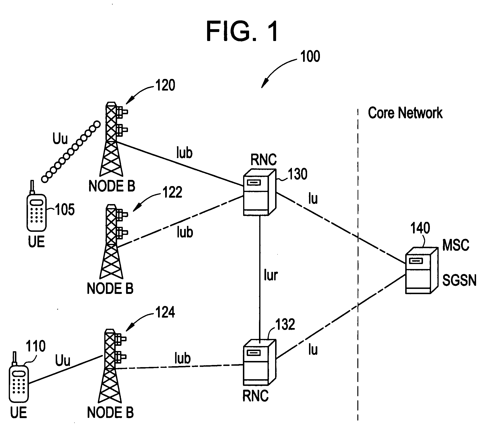
[0023]Example embodiments of the present invention will be described with respect to the UMTS system illustrated in FIG. 1. However, it will be understood that the present invention is not limited to this system or to UMTS systems.

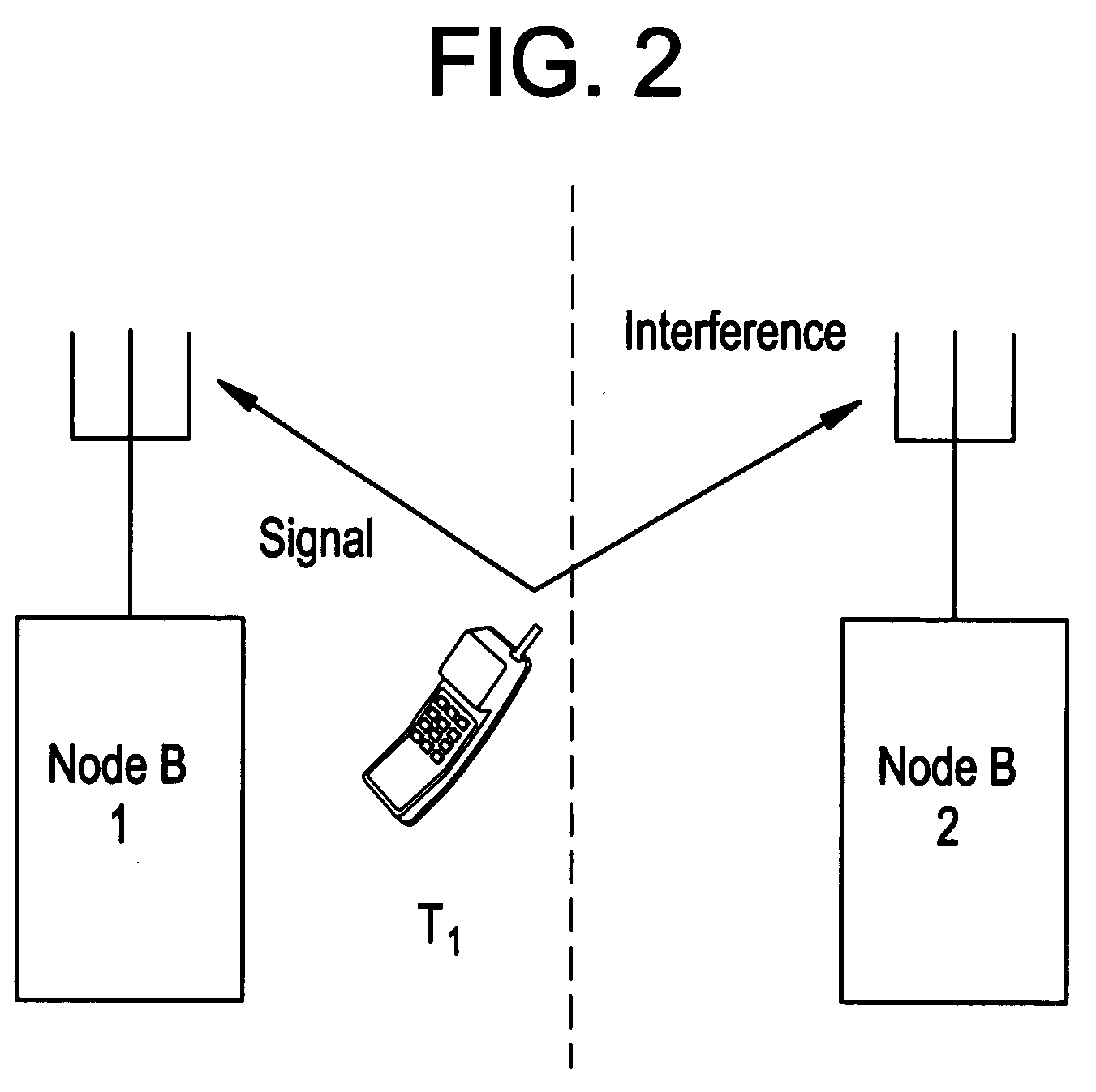
[0024]As discussed above, one problem with open loop fractional power is that it does not directly take into consideration the amount of interference a UE will generate to a neighbor cell / sector. For example, FIG. 2 illustrates an example where a UE may cause interference in a neighboring cell / sector (hereinafter collectively referred to as a cell). In FIG. 2, UE T1 is served by Node-B 1 and generates interference to Node-B 2. However, if UE T1 has a strong shadow fade to Node-B 2, then it should be allowed to transmit at a higher transmit power spectral density as compared to the case when UE T1 has a small shadow fade to Node-B 2. Another example is the case of a non-homogeneous deployment in which Node-B 2 has a much larger cell radius, in which case UE...


PUM


Abstract

In one embodiment, a reverse link transmission power for a user equipment is determined based on a first path loss and a second path loss. The first path loss is path loss between a serving station and the user equipment, and the serving station serves the communication needs of the user equipment. The second path loss is path loss between a neighboring station and the user equipment, and the neighboring station neighbors the serving station.

Description

BACKGROUND OF THE INVENTION[0001]1. Field of the Invention[0002]Example embodiments of the present invention relate generally to reverse link power control in a wireless communications network.[0003]2. Description of the Related Art[0004]A cellular communications network typically includes a variety of communication nodes coupled by wireless or wired connections and accessed through different types of communications channels. Each of the communication nodes includes a protocol stack that processes the data transmitted and received over the communications channels. Depending on the type of communications system, the operation and configuration of the various communication nodes can differ and are often referred to by different names. Such communications systems include, for example, a Code Division Multiple Access 2000 (CDMA2000) system and Universal Mobile Telecommunications System (UMTS).[0005]UMTS is a wireless data communication and telephony standard which describes a set of pro...

Claims


Application Information

Patent Timeline
IPC IPC(8): H04B7/00
CPCH04W52/10H04W52/146H04W52/40H04W52/243H04W52/36H04W52/242
Inventor RAO, ANIL M.
Owner ALCATEL-LUCENT USA INC
Why Eureka
Try Eureka