High intensity focused ultrasound treatment head and system

Active Publication Date: 2008-07-10
ANGEL SCI & TECH CANADA
View PDF26 Cites 29 Cited by
  • Summary
  • Abstract
  • Description
  • Claims
  • Application Information

AI Technical Summary

Problems solved by technology

There are three typical causes of attenuation:energy losses due to expansion of the wave front,energy losses due to scattering, andenergy losses due to absorption in the medium.
In common tap water, bubble and impurities in the water can cause scattering and make the ultrasonic energy attenuated.
For instance, redistribution of the energy internal and external to the molecule, molecular structure change and chemical change, etc., can cause sound energy consumption.
Its foundation is based on the fact that the acoustic impedance value of tissue is not uniform.
Some of these earlier systems would take an unacceptably long time to treat the target tissue, which may require the patient to be sedated or otherwise immobilized to keep the target tissue still for the long periods of time required for treatment.
Some of these earlier systems would require many hours of treatment to treat a large sized tissue mass.
A secondary harmonic may appear and damage tissue that is not an intended part of the treatment.
Phased arrays also may have quality control and cost issues related to producing a completely consistent set of transducer elements.
Each transducer element has to be thoroughly checked for quality control, adding significantly to the cost of such a system.
In addition, these minor variances between transducer elements may lead to difficulties in getting all the transducers in the array to fire simultaneously, to ensure that the resulting waves are properly in phase.
Minor variances may cause the waves to be out of phase, degrading the performance of the phased array.
Ultrasonic energy will attenuate while transmitting in tissue

Method used


Image

  • High intensity focused ultrasound treatment head and system
  • High intensity focused ultrasound treatment head and system
  • High intensity focused ultrasound treatment head and system

Examples


Embodiment Construction

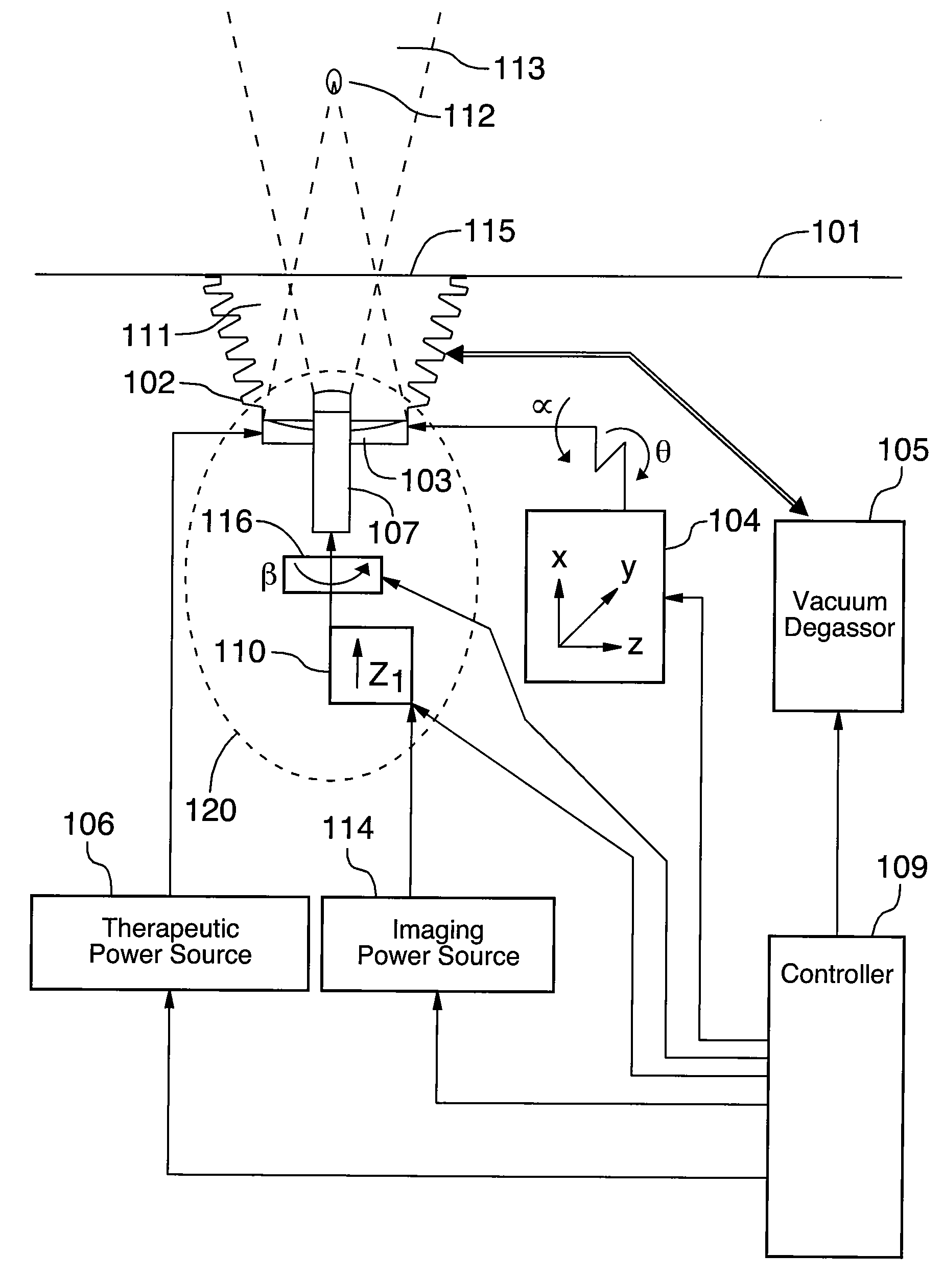
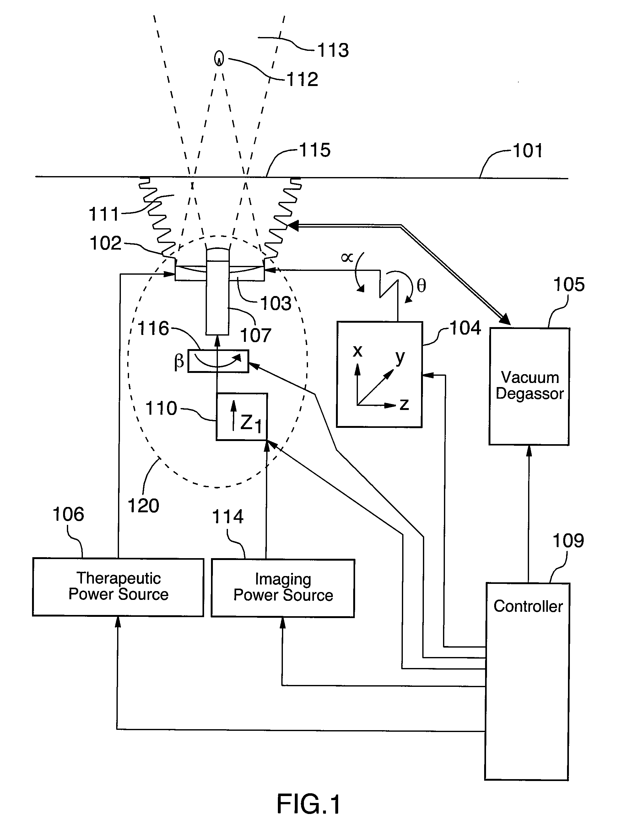
[0108]FIG. 1 is a schematic of the structure of the system according to the invention. The system comprises a therapeutic bed 101, a chamber 102, a combined head 120, a motional apparatus 104, a therapeutic power source 106, an imaging power source 114, a vacuum degassor 105, and a controller 109.

[0109]The therapeutic transducer 103, the imaging transducer 107, and a rotator 116, together form the combined head 120. The combined head 120 may also include an actuator 110.

[0110]The patient lies on the therapeutic bed 101, oriented to present the best access to the target tissue. Typically, but not always, this requires the patient to be placed with the skin closest to the target tissue over the hole 115 in the bed 101. The hole 115 is connected to a chamber filled with a fluid 111 having sound transmission characteristics similar to that of human tissue. Typically, the fluid 111 is degassed water which is gravity fed into the chamber from the vacuum degassor 105, as directed by the co...


PUM


Abstract

The system comprises a therapeutic bed, a chamber, a combined head, a motional apparatus, a therapeutic power source, an imaging power source, a vacuum degassor, and a controller. The therapeutic transducer, the imaging transducer, and a rotator, together form the combined head. The combined head may also include an actuator. The rotator and actuator move the imaging transducer relative to the therapeutic transducer. The therapeutic transducer produces high intensity focused ultrasound, and treats target tissue in the body.

Description

BACKGROUND OF THE INVENTION[0001]1. Field of the Invention[0002]The present invention relates to high intensity focused ultrasound (HIFU), and a system for treatment using HIFU.[0003]2. Description of the Related ArtUltrasound[0004]Sound waves are mechanical waves, typically generated by vibration, that propagate in a transmission medium such as air, water or human tissue. A sound wave may be categorized as follows based on its frequency:[0005]a sound wave less than the lower limit of human hearing, typically 16 Hz, is called an infrasonic wave or infrasound;[0006]a sound wave within the range of human hearing, typically from 16 Hz to 20 KHz, is called an acoustic wave; and[0007]a sound wave greater than the upper limit of human hearing, typically greater than 20 KHz, is called an ultrasonic wave or ultrasound;[0008]Ultrasonic waves can transmit higher energy than acoustic waves. For example: a 1 MHz ultrasonic wave of the same amplitude as a 1 KHz acoustic wave transmits 100 times ...

Claims


Application Information

Patent Timeline
IPC IPC(8): A61B8/00
CPCA61N7/02A61B2019/5276A61B2090/378
Inventor QIAN, MIN KANGHONG, YU BEIRUI, KAN
Owner ANGEL SCI & TECH CANADA
Why Eureka
Try Eureka