Eureka AIR delivers breakthrough ideas for toughest innovation challenges, trusted by R&D personnel around the world.

Communication device, radio communication terminal, radio base station and communication method

Inactive Publication Date: 2008-07-10
NTT DOCOMO INC
View PDF2 Cites 3 Cited by
  • Summary
  • Abstract
  • Description
  • Claims
  • Application Information

AI Technical Summary

Benefits of technology

[0018]In consideration of the forgoing problems, the present invention aims to provide a communication device and a communication method that are capable of largely increasing the probability that data retransmitted by a transmitter will be successfully received, and to provide a radio communication terminal and a radio base station each including the communication device.
[0020]According to this aspect, the transmitter is instructed to improve the transmission quality of the transmitter before the retransmission timing. Accordingly, a probability of successfully receiving a data piece retransmitted by the transmitter can be enhanced to a large extent.
[0028]The present invention makes it possible to provide a communication device and a communication method capable of largely enhancing a probability of successfully receiving data retransmitted by a transmitter, and also to provide a radio communication terminal and a radio base station each including the communication device.

Problems solved by technology

On the other hand, when the transmission power from a radio base station is too high, a transmission signal of a certain radio communication terminal interferes with a transmission signal of another radio communication terminal.
However, in the following cases (1) and (2), the foregoing transmission power control does not function properly.
As a result, even when the radio base station retransmits a data packet (hereinafter, called a PDU as needed), the retransmitted PDU is sometimes lost in a radio communication section, and this does not allow a receiver to receive the retransmitted PDU.
As a result, the PDU is retransmitted so excessively that a problem arises that the buffer capacity and radio resources are wastefully consumed.
As a result, the radio base station and the radio communication terminal get out of synchronization, and thereby are disabled to continue communicating with each other.

Method used


Image

  • Communication device, radio communication terminal, radio base station and communication method
  • Communication device, radio communication terminal, radio base station and communication method
  • Communication device, radio communication terminal, radio base station and communication method

Examples


first embodiment

(Schematic Configuration of Mobile Communication System)

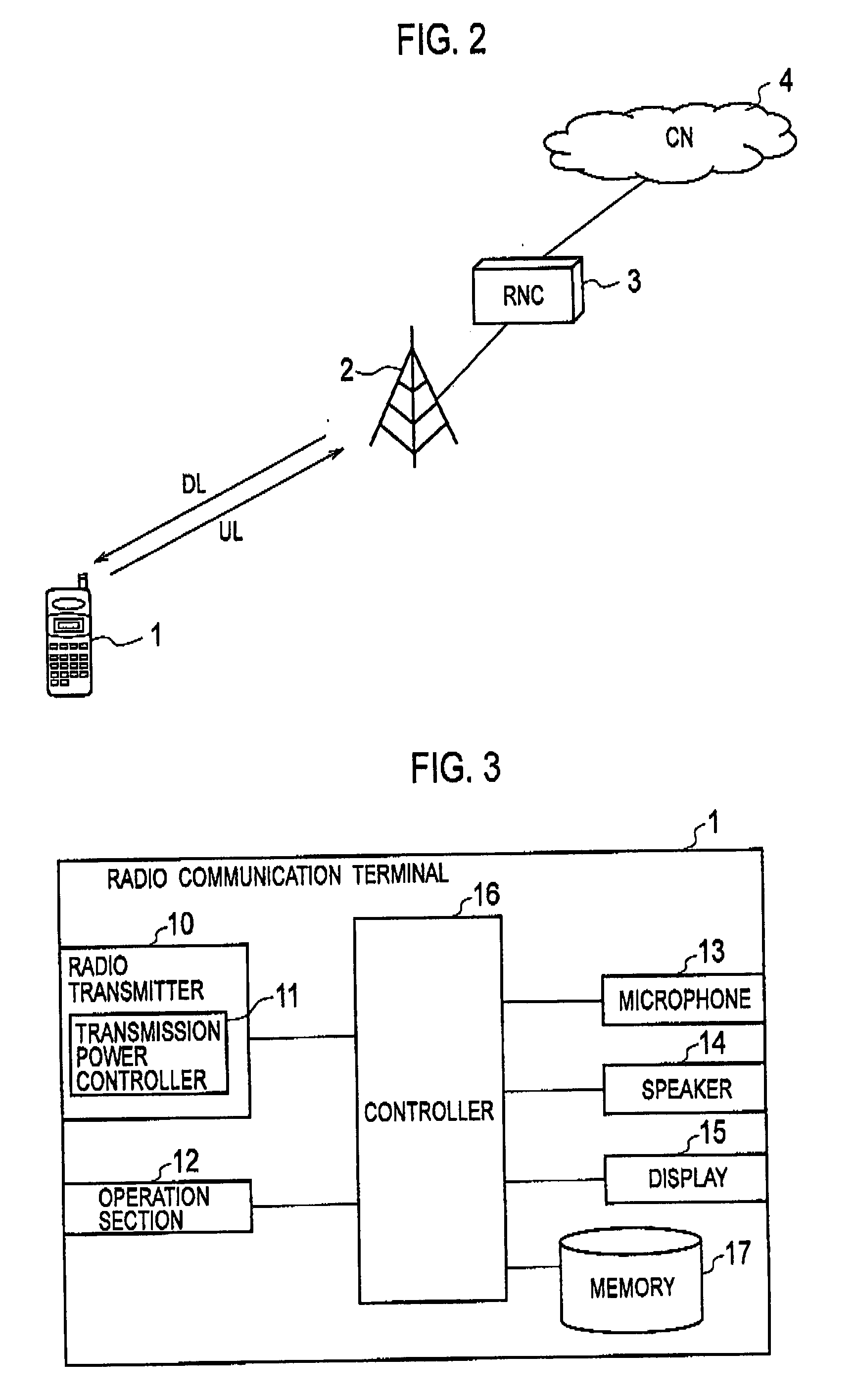
[0040]FIG. 2 is an entire schematic configuration of a mobile communication system according to this embodiment. This mobile communication system is one using the W-CDMA scheme.

[0041]As shown in FIG. 2, the mobile communication system includes a radio communication terminal 1, a radio base station 2, a radio network controller (called a “RNC” below) 3 and a core network (called a “CN” below) 4.

[0042]The radio communication terminal 1 establishes a radio link with the radio base station 2 when existing in the radio area of the radio base station 2, and communicates with another communication device via the CN 4. The radio communication terminal 1 controls the transmission power of the radio base station 2 in a downlink DL by use of the closed loop transmission power control.

[0043]The radio base station 2 has radio resources controlled by the RNC 3 and performs radio communications with the radio communication terminal 1. The rad...

second embodiment

[0095]In a second embodiment, the points different from the aforementioned first embodiment are mainly explained. A mobile communication system according to this embodiment is configured in the same manner as in FIG. 2. In addition, a radio communication terminal 1 according to this embodiment has the same configuration as in FIGS. 3 and 4 except for a controller 16.

(Configuration of Controller)

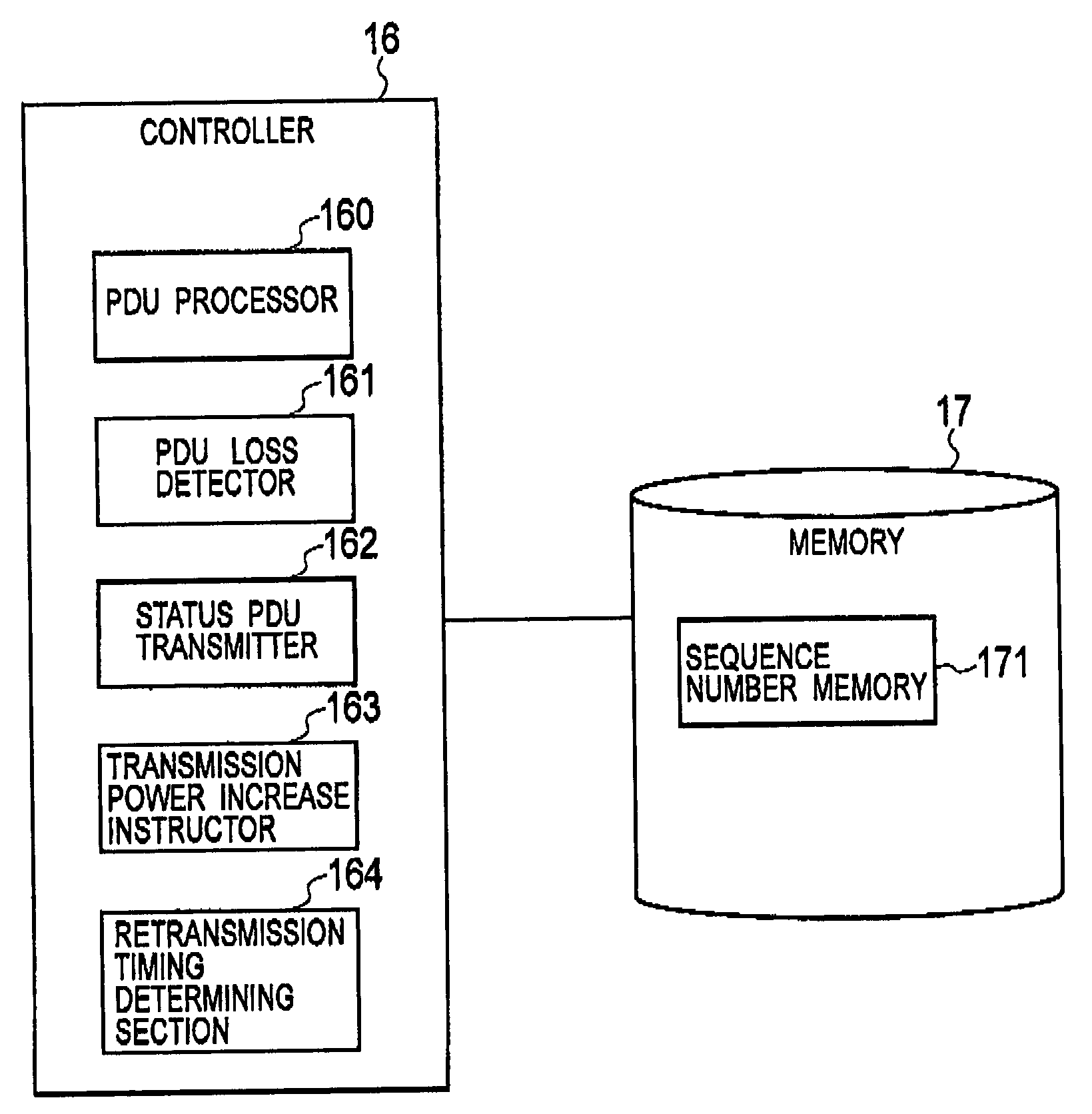
[0096]FIG. 8 is a functional block diagram showing a configuration of the controller 16 of the radio communication terminal 1 according to this embodiment.

[0097]As shown in FIG. 8, the controller 16 of this embodiment is different from that of the aforementioned first embodiment in that the controller 16 includes a retransmission timing determining section 164 configured to determine (estimate) a retransmission timing in the radio base station 2.

[0098]When a PDU loss detector 161 detects a PDU loss, the retransmission timing determining section 164 determines (estimates) the PDU retransmissio...


PUM


Abstract

The present invention aims to largely improve a probability of successfully receiving a PDU retransmitted by a transmitter. To this end, provided is a communication method for continuously receiving multiple PDUs from a radio base station via a radio link. The method includes the steps of: determining whether or not any one of the multiple PDUs is lost; and making an instruction to the radio base station to increase the transmission power of the radio base station when it is determined that any one of the multiple PDUs is lost, the instruction being made before a retransmission timing when the transmitter retransmits the lost data piece.

Description

CROSS REFERENCE TO RELATED APPLICATION[0001]This application is based upon and claims the benefit of priority from prior Japanese Patent Application P2007-000245 filed on Jan. 4, 2007; the entire contents of which are incorporated by reference herein.BACKGROUND OF THE INVENTION[0002]1. Field of the Invention[0003]The present invention relates to a communication device and a communication method for continuously receiving multiple data (data packets) from a transmitter via a radio link, and relates to a radio communication terminal and a radio base station each including the communication device.[0004]2. Description of the Related Art[0005]Heretofore, in radio communications, a transmission power control technique has been used to control the transmission powers of a radio communication terminal and a radio base station. Precisely, in a downlink, a phenomenon called fading occurs in which the received power of a radio communication terminal suddenly fluctuates due to a movement of th...

Claims


Application Information

Patent Timeline
IPC IPC(8): H04L1/18G06F11/16H04W52/06H04W52/08H04W52/12H04W52/14H04W52/48
CPCH04L1/1685H04L1/1825H04L1/1848H04L1/188H04W52/48H04W52/08H04W52/12H04W52/14H04W52/06
Inventor OKAMOTO, ETSUHIROOKUMURA, YUKIHIKOKITAYAMA, TETSUROEBARA, HIDETOSHI
Owner NTT DOCOMO INC
Why Eureka
Eureka Blog
Learn More