Plasma generating apparatus

a technology of generating apparatus and plasma, which is applied in the direction of plasma technique, coating, energy-based chemical/physical/physicochemical process, etc., can solve the problems of deteriorating productivity, 10 mt, and great difficulty in generating and maintaining plasma

Inactive Publication Date: 2008-07-17
JEHARA CORP
View PDF24 Cites 15 Cited by
  • Summary
  • Abstract
  • Description
  • Claims
  • Application Information

AI Technical Summary

Benefits of technology

0]The plasma generating apparatus may further include a gas distribution plate provided at a bottom of the insulating vacuum plate and enabling a uniform downward distribution of a gas injected through the gas injection port.BRI

Problems solved by technology

However, the CCP type plasma generating apparatus has a disadvantage in that it has a great difficulty in generating and sustaining plasma at the low pressure of 10 mT or less.
The CCP type plasma generating apparatus has a disadvantage in that productivity deteriorates because the low plasma density results in a reduction of etch rate and deposition rate.
However, the ICP type plasma generating apparatus has a disadvantage in that it has a difficulty in acquiring a uniform plasma density because a point to which an RF power is applied and a ground point from which an electric current flows out are separated from each other and thus, there is an electric potential between both ends.
However, the ICP type plasma generating apparatus has a limitation to a large-sized diameter and has a difficulty in guaranteeing large-scale plasma uniformity though the large-scale plasma uniformity should be guaranteed for an LCD device greater than for a semiconductor.
This leads to getting longer a residence time of a reaction gas injected into the chamber.
The long residence time of the injected reaction gas leads to an increase of a gas ionization rate and a generation of more complex radical than in the CCP type plasma generating apparatus, thereby getting inappropriate to recent semiconductor and LCD processes requiring a delicate radical control.
However, the ICP type plasma generating apparatus has a drawback that it cannot generate uniform density plasma at a high pressure of 100 mT to 10 T where poor plasma diffusion is implemented.

Method used


Image

  • Plasma generating apparatus
  • Plasma generating apparatus
  • Plasma generating apparatus

Examples


Embodiment Construction

[0068]Exemplary embodiments of the present invention will now be described in detail with reference to the annexed drawings. In the following description, a detailed description of known functions and configurations incorporated herein has been omitted for conciseness.

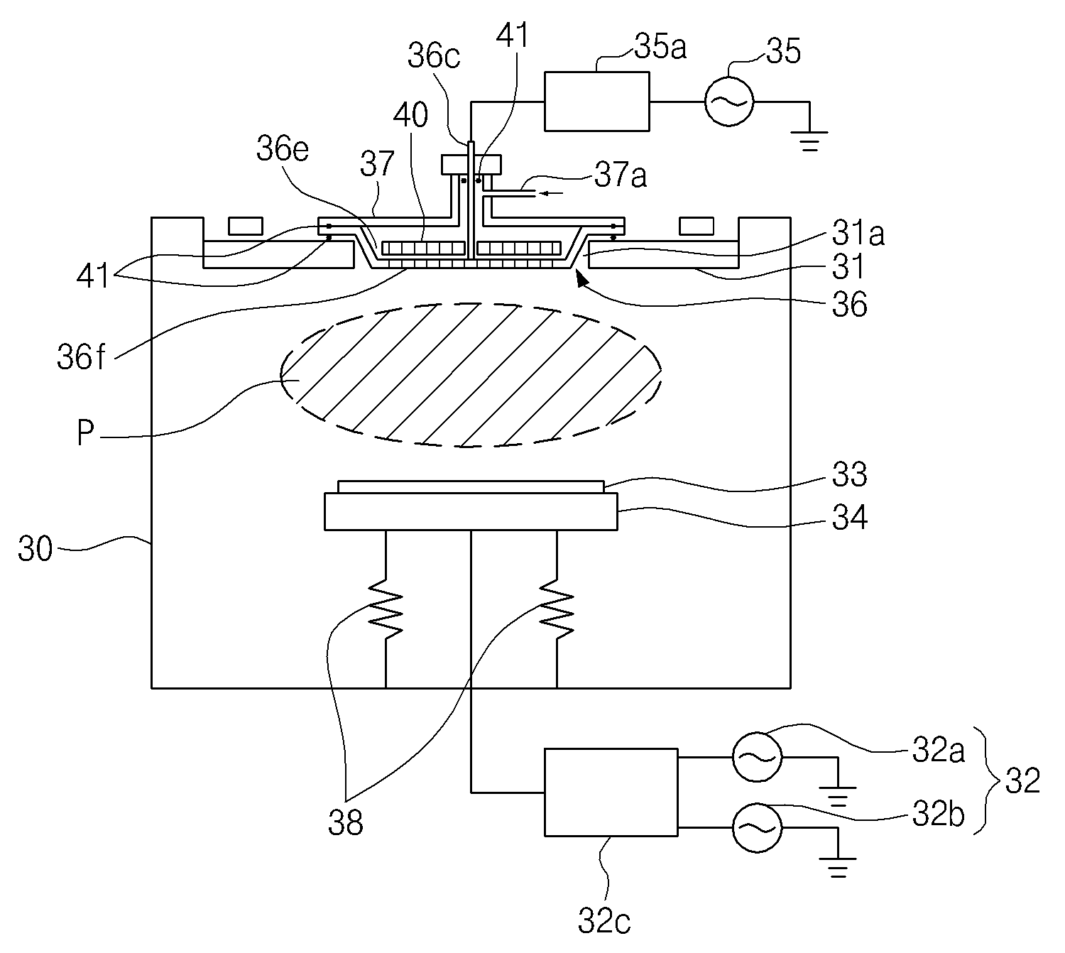
[0069]FIG. 3 is a schematic cross-sectional view illustrating a plasma generating apparatus according to an exemplary embodiment of the present invention. FIG. 4 is a plan view of FIG. 3. FIG. 5 is a cross-sectional view taken along line A-A′ of FIG. 4. FIG. 6 is a schematic circuit diagram illustrating an equivalent circuit of the plasma generating apparatus according to an exemplary embodiment of the present invention.

[0070]As shown in FIGS. 3 to 6, the plasma generating apparatus includes a vacuum chamber 30 whose interior is hollow and whose top is sealed by an insulating vacuum plate 31; an ElectroStatic Chuck (ESC) 34 disposed at an internal center of the vacuum chamber 30 and placing a substrate 33 thereon; an a...


PUM

PropertyMeasurementUnit
pressureaaaaaaaaaa
sizeaaaaaaaaaa
diameteraaaaaaaaaa

Abstract

Provided is a plasma generating apparatus. The plasma generating apparatus includes a vacuum chamber, an ElectroStatic Chuck (ESC), an antenna unit, and an antenna cover. The vacuum chamber has a hollow interior and is sealed at a top. The ESC disposed at an internal center of the vacuum chamber receives an external bias Radio Frequency (RF). The antenna unit covers and seals the through-hole of an insulating vacuum plate. The antenna cover covers a top of the antenna unit and has a gas injection port.

Description

CROSS REFERENCE[0001]This application claims foreign priority under Paris Convention and 35 U.S.C. §119 to each of Korean Patent Application No. 10-2007-0004100, filed Jan. 15, 2007, and No. 10-2007-0027984, filed Mar. 22, 2007 with the Korean Intellectual Property Office.BACKGROUND OF THE INVENTION[0002]1. Field of the Invention[0003]The present invention relates to a plasma generating apparatus. More particularly, the present invention relates to a plasma generating apparatus in which an antenna unit has a composite structure with a plate shape antenna and a coil shape antenna and an ElectroStatic Chuck (ESC) elevates and descends to control a capacitance with the antenna unit, thereby selectively forming an electric field and a magnetic field within a chamber as well as to control even an RF power transmission rate, thereby providing a large-scale high-density plasma with uniform density under both conditions where a gap is provided narrow and wide between the ESC and the antenna...

Claims


Application Information

Patent Timeline
Patent Type & Authority Applications(United States)
IPC IPC(8): H05H1/00C23C16/00H01L21/306
CPCH01J37/32082H01J37/32091H01J37/321H01J37/32733H01L21/67069H01L21/6833H05H1/46
Inventor KIM, HONG-SEUB
Owner JEHARA CORP
Why Eureka
Try Eureka