Diaphragm for Turbomachines and Method of Manufacture

a technology of diaphragm and turbomachine, which is applied in the direction of liquid fuel engines, vessel construction, marine propulsion, etc., can solve the problem of reducing the total pressure load of the turbine working fluid on the diaphragm, and achieves the effect of reducing welding and material requirements, good predictability of dynamic behaviour in operation, and equivalent static strength

Active Publication Date: 2008-07-17
GENERAL ELECTRIC TECH GMBH
View PDF7 Cites 29 Cited by
  • Summary
  • Abstract
  • Description
  • Claims
  • Application Information

AI Technical Summary

Benefits of technology

[0019]The above features result in a diaphragm having reduced welding and material requirements in comparison with

Problems solved by technology

Furthermore, elimination of the inner diaphragm ring, with accompanying increase in the radius of the turbine rotor aga

Method used


Image

  • Diaphragm for Turbomachines and Method of Manufacture
  • Diaphragm for Turbomachines and Method of Manufacture
  • Diaphragm for Turbomachines and Method of Manufacture

Examples


Embodiment Construction

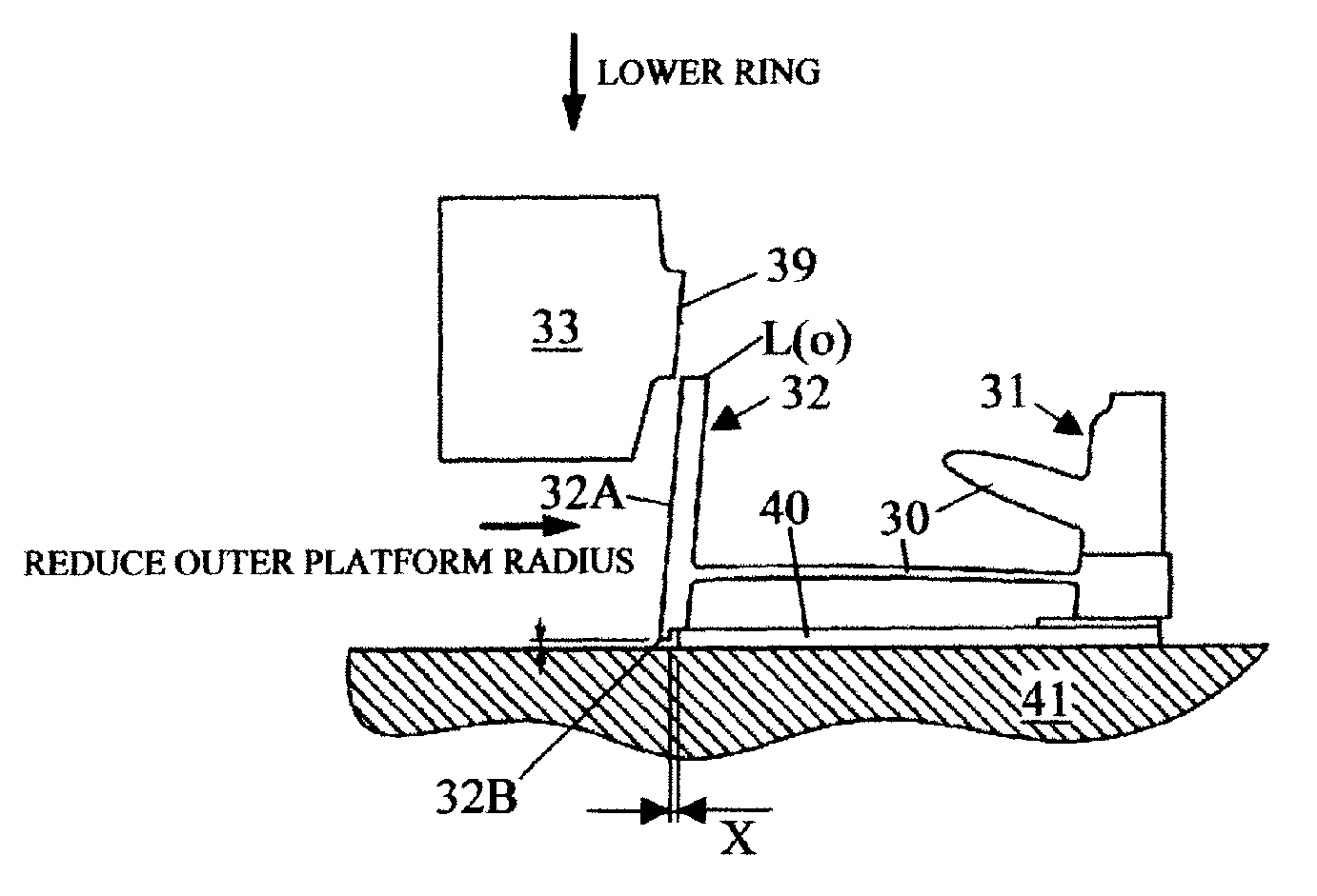
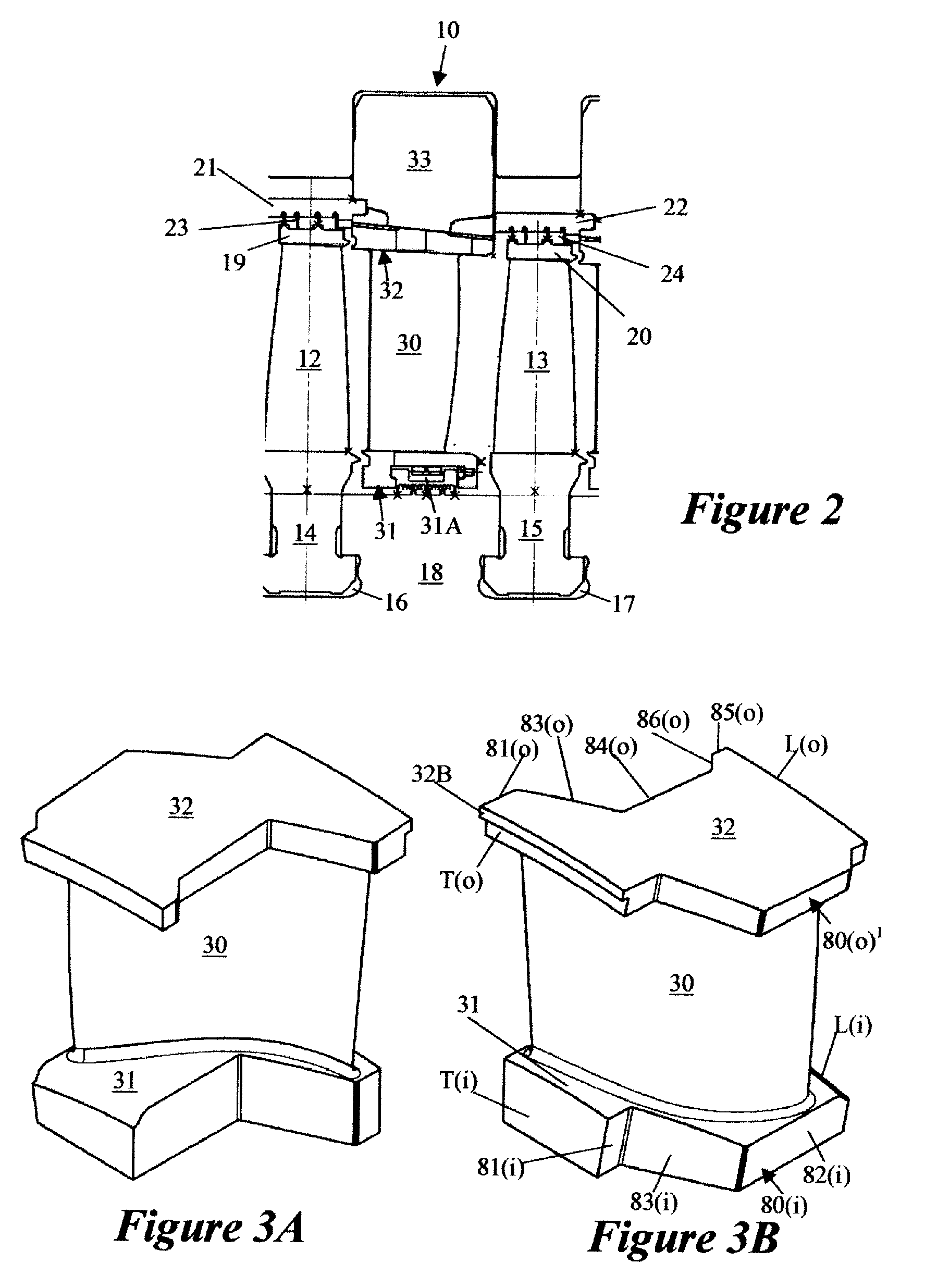
[0032]FIG. 2 is partial radial sectional sketch of an embodiment of the invention, showing a fully assembled diaphragm 10 located between successive annular rows of moving blades 12, 13 in a steam turbine. The moving blades are each provided with radially inner “T-root” portions 14, 15 located in corresponding slots 16, 17 machined in the rim of a rotor drum 18. They are also provided with radially outer shrouds 19, 20 that seal against circumscribing segmented rings 21, 22. As known, sealing between the 19, 20 shrouds and the rings 21, 22 is accomplished by fins 23, 24, which are caulked into grooves machined in the rings 21, 22.

[0033]Diaphragm 10 comprises an annular row of static blades, each having an aerofoil 30 whose radially inner and outer ends are integral with radially inner and outer platforms 31, 32, respectively. FIGS. 3A and 3B are pictorial views of the opposite sides of a static blade before it is assembled into a diaphragm, showing the shapes of the inner and outer ...


PUM

PropertyMeasurementUnit
Fractionaaaaaaaaaa
Lengthaaaaaaaaaa
Angleaaaaaaaaaa

Abstract

A turbine diaphragm includes an annulus of static blades and an outer diaphragm ring surrounding the annulus of static blades and welded to the outer platforms. Each static blade has an inner platform, an aerofoil, and an outer platform. The inner platforms serve the function of an inner diaphragm ring, thereby reducing material and manufacturing costs. Furthermore, confronting edges of the inner platforms have an interference fit with each other and the aerofoils are in a state of torsional stress between the inner and outer platforms. The latter two features improve the dynamic characteristics of the diaphragm.

Description

[0001]This application claims priority under 35 U.S.C. §119 to U.S. Provisional application No. 60 / 880,273, filed 12 Jan. 2007, the entirety of which is incorporated by reference herein.BACKGROUND[0002]1. Field of Endeavor[0003]The present invention relates to a novel construction for diaphragms of the type used in axial flow turbomachines. It is particularly, but not exclusively, relevant to steam turbine diaphragms.[0004]2. Brief Description of the Related Art[0005]The present invention is related to the so-called “platform” type of diaphragm construction, see FIGS. 1A and 1B. FIG. 1A is a perspective view of a static blade or vane, and FIG. 1B is a view on a radial section of a diaphragm during manufacture, including the static blade. In this type of diaphragm, the ends of the aerofoils 1 are integral with radially inner and outer “platforms”2, 3, the aerofoils and platforms being machined from solid. In FIG. 1A, an adjacent blade shape is shown in dashed lines, a complete annulu...

Claims


Application Information

Patent Timeline
IPC IPC(8): F01D1/02B23P17/00
CPCF01D9/041Y10T29/49229F01D25/246
Inventor PALMER, BRYAN ROYLITTLEWOOD, DAVIDBLATCHFORD, DAVID PAULCRITCHLEY, PETER FRANKLORD, ADRIAN
Owner GENERAL ELECTRIC TECH GMBH
Why Eureka
Try Eureka