System and method for spinal instrumentation

Inactive Publication Date: 2008-07-17
KRAEMER PAUL EDWARD
View PDF11 Cites 11 Cited by
  • Summary
  • Abstract
  • Description
  • Claims
  • Application Information

AI Technical Summary

Benefits of technology

[0028]An advantage of the present invention is that it preserves vascularity and innervation of the first superjacent facet, minimizing the likelihood of facet disease and adjacent segment disease.
[0029]Another advantage of the present invention is that it is usable with limited surgical exposure.
[0030]A further advantage of the present invention is that it has reduced prominence, thereby reducing patient pain and enhancing the usability of the spinal instrumentation system at the thoracolumbar junction and in thinner patients.
[0031]Yet another advantage of the present invention is that it is suitable for use in multilevel fusions.
[0032]Still another advantage of the present invention is that it can be rigidly locked simply and efficiently.

Problems solved by technology

Existing spinal instrumentation systems often present surgical difficulties when used in the superior (that is, the most cranial) segment of the region to be fused.
Such difficulties include facet disease and adjacent segment disease, which may result from damage to the vascularity and innervation of the first cranial non-fused segment.
In addition, spinal instrumentation procedures are often invasive, traumatic, and painful for the patient.

Method used


Image

  • System and method for spinal instrumentation
  • System and method for spinal instrumentation
  • System and method for spinal instrumentation

Examples


Embodiment Construction

[0054]The present invention provides devices and methods for rigidly connecting articulated elements. For the sake of explanation, the present invention will be described in connection with orthopedic or neurosurgical spinal surgery, more particularly in the context of spinal instrumentation, and most particularly with reference to instrumentation of the superior (that is, most cranial) segment in a lumbar fusion procedure. One of ordinary skill in the art will appreciate, however, that the teachings disclosed herein may be applied to good advantage in other contexts where it is desirable to rigidly connect articulated elements.

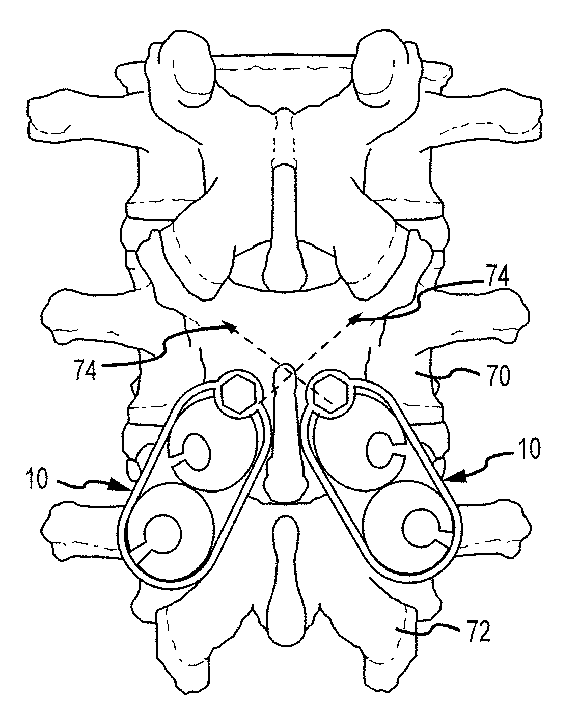
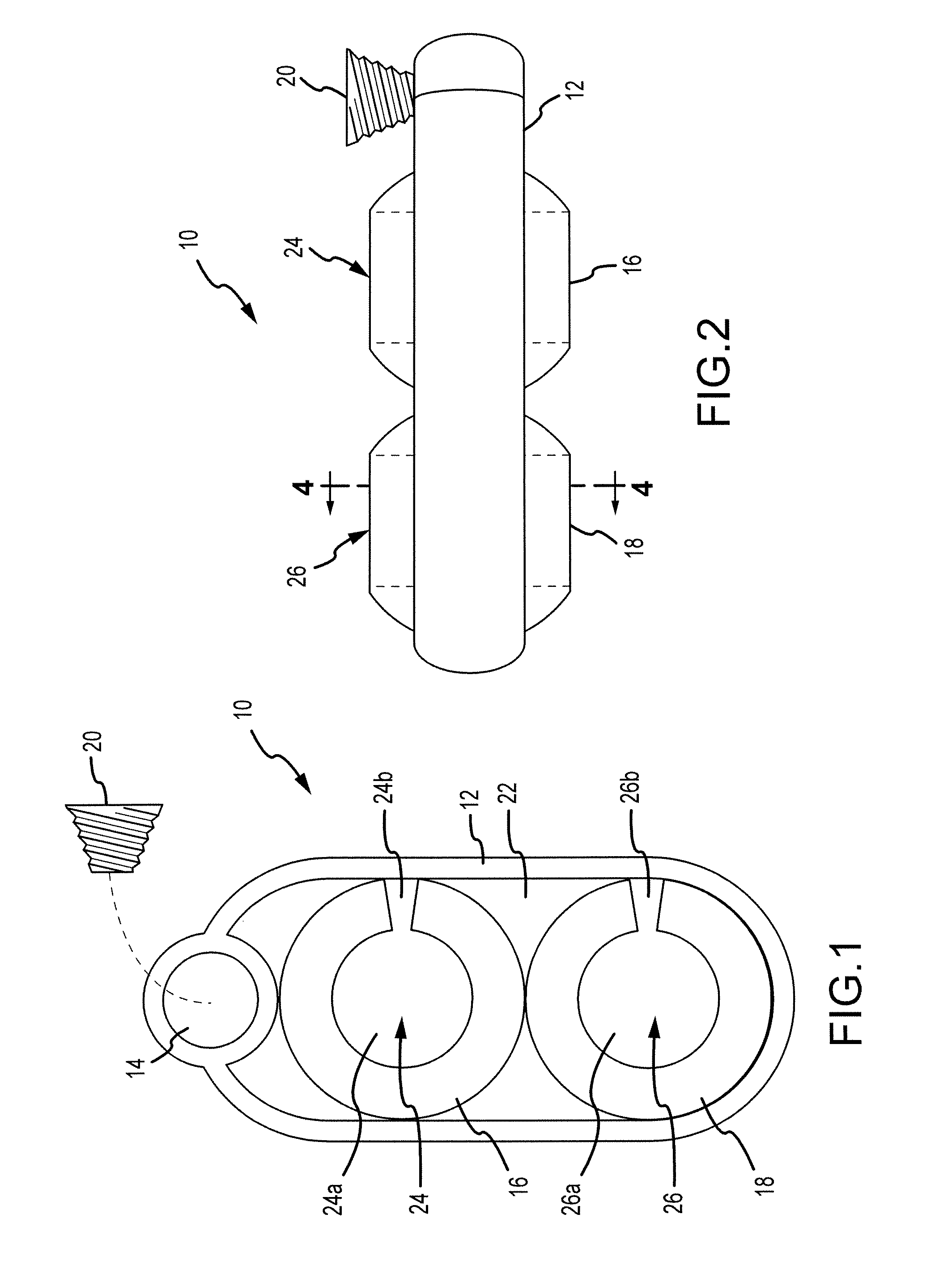
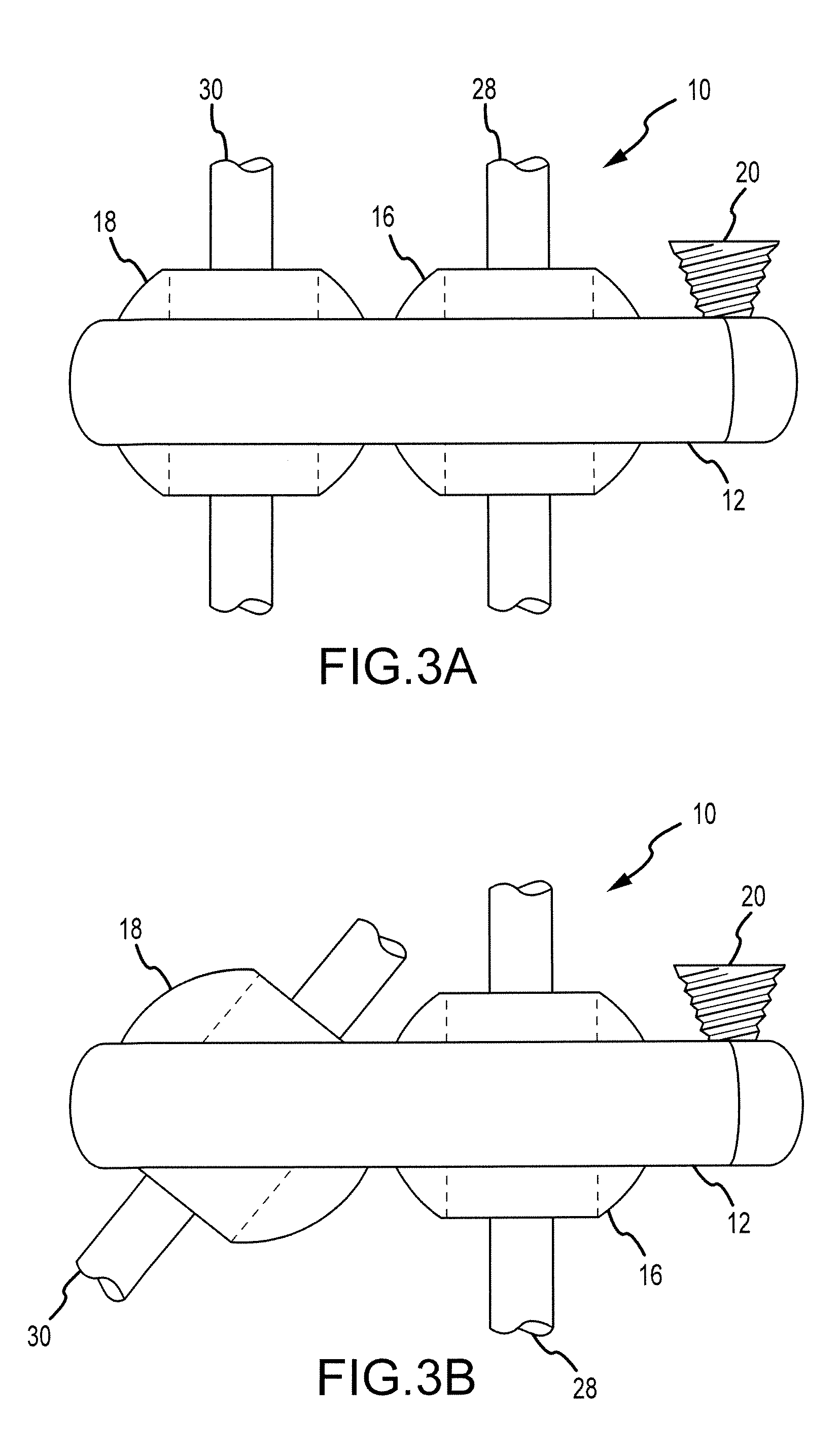
[0055]FIG. 1 schematically illustrates a spinal instrumentation system 10 according to one embodiment of the present invention. Spinal instrumentation system 10 generally includes a tension ring 12 including a tensioning device receptacle 14, a first compression ball 16, and a second compression ball 18. Spinal instrumentation system 10 also includes a tensio...


PUM


Abstract

A spinal instrumentation system includes an oblong tension ring having a tension screw receptacle, a pair of compression balls having passages therethrough disposed within the tension ring, and a tension screw. Threading the tension screw into the tension screw receptacle inhibits movement of the compression balls relative to the tension ring and each other, thereby making the system rigid. Fixation screws are inserted through the passages in the compression balls and anchored in bone. One of the fixation screws may be a screw designed to traverse the lamina and including a scalloped segment. A pair of such systems may be posteriorly attached to the vertebrae, one on either side of the spinous process, to fuse the superior segment in a lumbar fusion procedure. The spinal fixation screws traverse the lamina, crossing at their scalloped segments.

Description

CROSS-REFERENCE TO RELATED APPLICATIONS[0001]This application claims the benefit of United States provisional application no. 60 / 880,066, filed 12 Jan. 2007, and United States provisional application no. 60 / 929,758. The instrumenting are hereby incorporated by reference as though fully set forth herein.BACKGROUND OF THE INVENTION[0002]a. Field of the Invention[0003]The instant invention relates to generally to orthopedic surgery, and more specifically to spinal fusion surgery. More particularly, the instant invention relates to devices for and methods of instrumenting the superior segment in a lumbar fusion procedure.[0004]b. Background Art[0005]The spinal column is a complex system of bones and connective tissue that protects critical elements of the nervous system. Though complex, the spine is a highly flexible structure, capable of a high degree of curvature and twist through a wide range of motion.[0006]It is known to attempt to correct spinal defects and restore stability to th...

Claims


Application Information

Patent Timeline
IPC IPC(8): A61B17/70A61B17/80A61B17/86
CPCA61B17/8625A61B17/7007
Inventor KRAEMER, PAUL EDWARD
Owner KRAEMER PAUL EDWARD
Why Eureka
Try Eureka