Time Interval Measuring Apparatus and Jitter Measuring Apparatus Using the Same

a time interval measuring and jitter measurement technology, applied in the direction of noise figure or signal-to-noise ratio measurement, instruments, pulse characteristics measurement, etc., can solve the problems of large changes in error, difficult to adopt such a measurement method, and inability to maintain precision over a long time. , to achieve the effect of high precision, high precision of jitter measurement, and sufficient jitter amoun

Inactive Publication Date: 2008-07-17
ANRITSU CORP
View PDF4 Cites 7 Cited by
  • Summary
  • Abstract
  • Description
  • Claims
  • Application Information

AI Technical Summary

Benefits of technology

[0043]In order to solve the problem of the prior art as described above, an object of the present invention is to provide a time interval measuring apparatus which is capable of accurately and stably measuring an input interval time of a pulse signal with a high precision, and a jitter measuring apparatus using the time interval measuring apparatus.
[0155]That is, the time interval measuring apparatus according to the first aspect of the present invention, in a prior art disclosed in the patent document 1 or the like, not only eliminates the need of the adjustment work of a circuit constant inside of the phase shifter which is required for setting the phase difference between the two signals output from the phase shifter to 90 degrees, but also is capable of correcting the phase error and the amplitude error generated in the phase shifter by means of the numeric value calculation with a combination of three kinds of errors such as the direct current offset errors, the phase error and the amplitude error which are generated in the first and second A / D converters at the rear stage of the phase shifter.
[0156]As a consequence, in accordance with the time interval measuring apparatus (20) according to the first aspect, it is possible to easily realize a time interval measuring apparatus having a precision of several hundreds of psec or less which cannot be realized in the prior art.
[0159]Furthermore, in accordance with a jitter measuring apparatus (40) according to the twelfth aspect of the present invention, a jitter amount is calculated based on the input interval time T measured with a high precision by the time interval measuring apparatus (20) according to the first aspect of the invention or by the time interval measuring apparatus (20′) according to the third aspect of the invention. As a consequence, the precision of the jitter amount is sufficiently high, and highly precise jitter measurement can be performed.

Problems solved by technology

Under these circumstances, it is difficult to adopt such a measurement method.
Besides, the error largely changes with environmental changes such as the frequency and temperatures.
Therefore, even if a circuit constant in the phase shifter 12 is adjusted at a certain frequency and under a certain environment to obtain a desired precision, it is impossible to maintain the precision over a long time.
However, in actuality, it is substantially impossible to prevent a change of the error characteristic by the phase shifter 12 having such a wideband characteristic.
Depending on differences in these characteristics, a phase error, an amplitude error and a direct current offset error may occur between the digital sample values I and Q.
In addition, even if the difference in delay time is eliminated by a delay process with respect to a pulse signal p which is input to the side of one of the A / D converters, it is impossible to obtain a long time precision owing to the characteristic change resulting from the temperature of the delay process unit.

Method used


Image

  • Time Interval Measuring Apparatus and Jitter Measuring Apparatus Using the Same
  • Time Interval Measuring Apparatus and Jitter Measuring Apparatus Using the Same
  • Time Interval Measuring Apparatus and Jitter Measuring Apparatus Using the Same

Examples


first embodiment

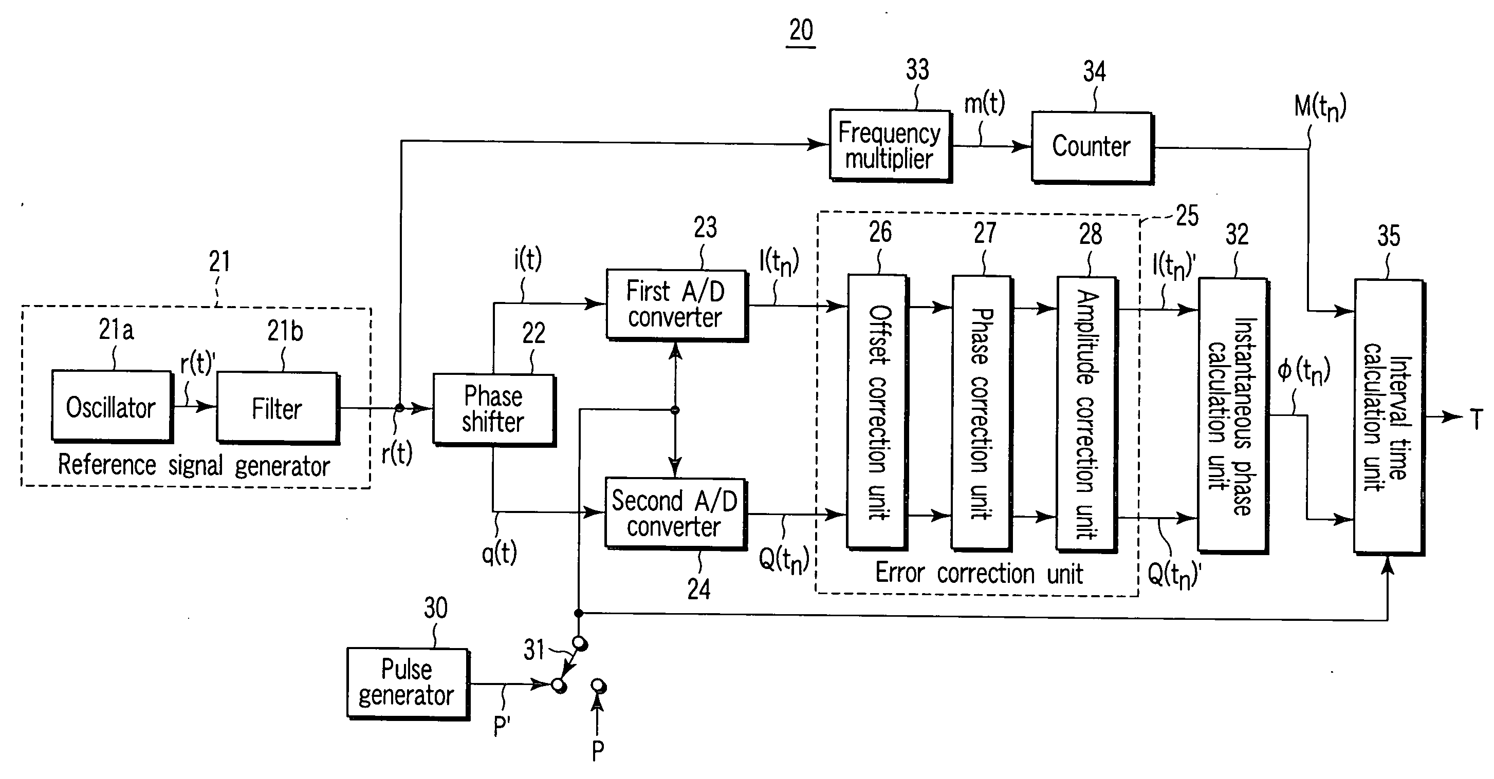
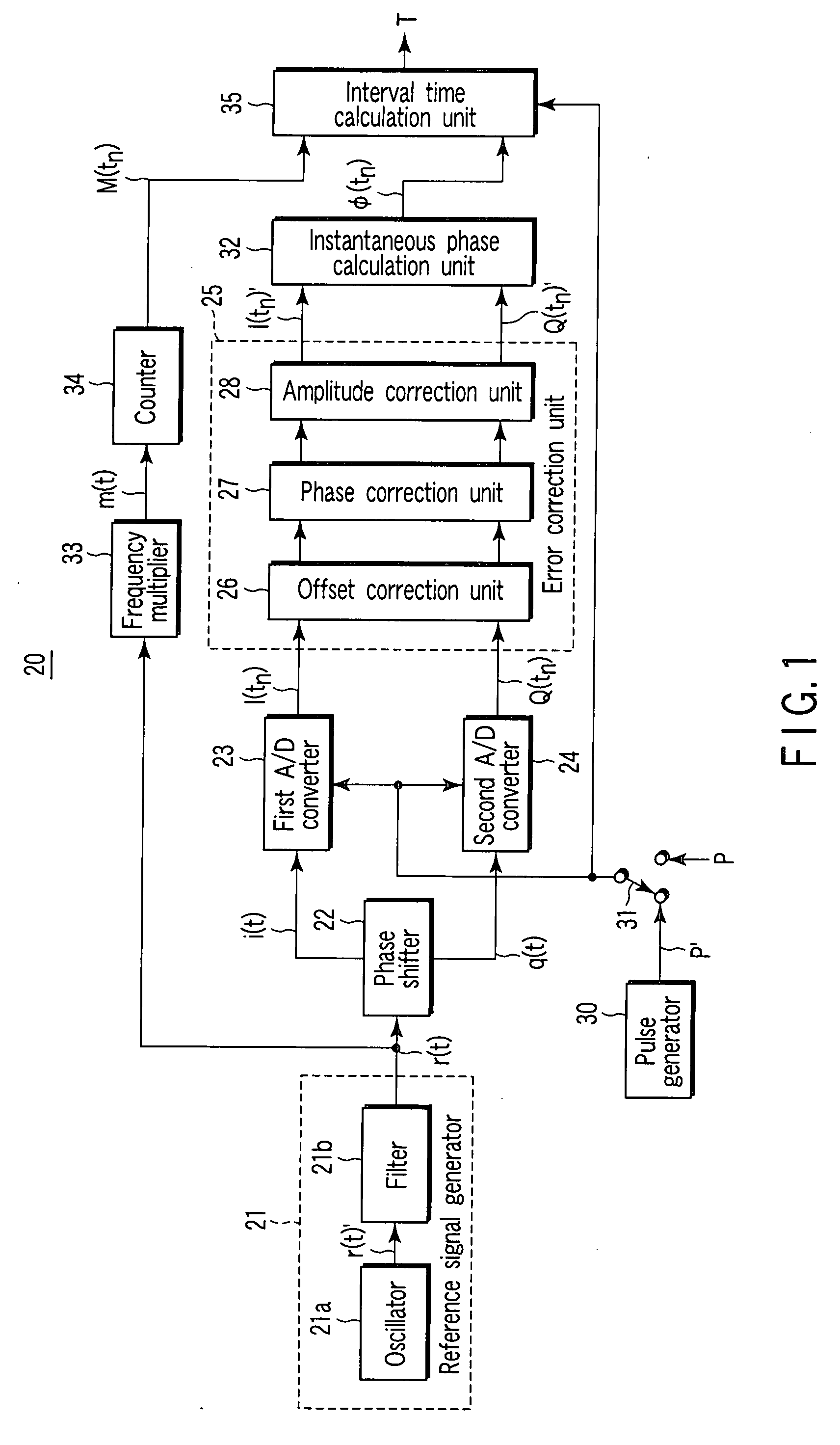
[0175]FIG. 1 is a block diagram showing a configuration of a time interval measuring apparatus 20 according to a first embodiment of the present invention.

[0176]That is, the time interval measuring apparatus according to the first embodiment of the present invention basically comprises a reference signal generator 21, a phase shifter 22, a first analog / digital (A / D) converter 23, a second A / D converter 24, an error correction unit 25, an instantaneous phase calculation unit 32, and an interval time calculation unit 35. The reference signal generator 21 generates a reference signal r(t) having a sine wave with a predetermined frequency. The phase shifter 22 receives the reference signal r(t) generated by the reference signal generator 21, and outputs a first analog signal i(t) and a second analog signal q(t) whose phases are shifted each other. The first A / D converter 23 performs sampling of the first analog signal i(t) which is output from the phase shifter at an input timing of a p...

second embodiment

[0275]The minimum measurement time Tmin of the time interval measuring apparatus 20 having a configuration according to the first embodiment is determined with an upper limit fmax of the sampling frequency of the A / D converters 23 and 24.

[0276]That is, the minimum measurement time is set to Tmin≧1 / fmax, with the result that there is a limitation that the input interval time which is shorter than the time described above cannot be measured.

[0277]Then, in a time interval measuring apparatus 20′ according to a second embodiment, as shown in FIG. 10, one set of the A / D converters 23 and 24, and the error correction units 25 and instantaneous phase calculation units 32 according to the first embodiment are provided as two sets respectively, whereby the lower limit of the measurement time can be eliminated.

[0278]More specifically, only with one set of A / D converters 23 and 24, the error correction unit 25 and the instantaneous phase calculation unit 32 according to the first embodiment, t...

third embodiment

[0291]FIG. 11A is a block diagram showing a configuration of a jitter measuring apparatus 40 according to a third embodiment of the present invention.

[0292]As shown in FIG. 11A, the jitter measuring apparatus 40 according to the third embodiment of the invention basically comprises a signal processing unit 42, the time interval measuring apparatus 20 according to the first embodiment described above or the time interval measuring apparatus 20′ according to the second embodiment (refer to FIG. 1 or 10), and a jitter calculation unit 41.

[0293]That is, the time interval measuring apparatuses 20 and 20′ configured according to the first and second embodiments is not simply constituted as a apparatus for interval time measurement. In addition, as shown in FIG. 11A, the jitter measuring apparatus 40 can be constituted by using the jitter calculation unit 41 for calculating a statistics amount with respect to jitters from a calculated time T, and the signal processing unit 42 for creating ...


PUM


Abstract

In order to stably measure an input interval time of a pulse signal with high precision, a time interval measuring apparatus includes a reference signal generator, a phase shifter, first and second A / D converters, an error correction unit, an instantaneous phase calculation unit, and an interval time calculation unit. The phase shifter divides a reference signal of a sine wave having a predetermined frequency from the reference signal generator into a first analog signal and a second analog signal having phases shifted to each other. The first and second A / D converters perform sampling of the first analog signal and the second analog signal from the phase shifter, respectively, at an input timing of a pulse signal to be measured, and output a first and second digital sample values. The error correction unit corrects direct current offset errors generated in, respectively, the first and second digital sample values output from the first and second A / D converters, a phase error with respect to 90°, and an amplitude error. The instantaneous phase calculation unit calculates an instantaneous phase of the reference signal based on the corrected first and second digital sample values. The interval time calculation unit determines an input interval time of the pulse signal based on a variation of instantaneous phases.

Description

TECHNICAL FIELD[0001]The present invention relates to a time interval measuring apparatus and a jitter measuring apparatus using the same. In particular, the present invention relates to a time interval measuring apparatus which adopts a technology for accurately measuring an input interval time of a pulse signal with a high resolution, and a jitter measuring apparatus which uses the time interval measuring apparatus.BACKGROUND ART[0002]As a technique for measuring a phase fluctuation (jitters) of a pulse signal such as a data signal or a clock signal, there is known a time interval measuring method for measuring an interval time between a rising portion and a falling portion of the pulse signal.[0003]In such a time interval measuring method, it is demanded that the measurement thereof should be more precise along with an increase in a data transmission rate in recent years.[0004]For example, since an interval between bits of a digital signal of 1 Gbps is 1 nsec, at least 100 psec o...

Claims


Application Information

Patent Timeline
Patent Type & Authority Applications(United States)
IPC IPC(8): G01R29/02
CPCG01R25/00G01R29/023G04F10/06G01R29/26G01R31/31709G01R29/0273
Inventor MOCHIZUKI, KENSUGIYAMA, OSAMUNISHIKOBARA, TADANORI
Owner ANRITSU CORP
Why Eureka
Try Eureka