
Pump drive structure of water-cooled internal combustion engine

Inactive Publication Date: 2008-07-24
HONDA MOTOR CO LTD
View PDF1 Cites 11 Cited by
  • Summary
  • Abstract
  • Description
  • Claims
  • Application Information

AI Technical Summary

Benefits of technology

[0010]In view of such problems, it is an object of an embodiment of the present invention to provide a pump drive structure of a water-cooled internal combustion engine in which the number of revolving shafts arranged in parallel to each other is reduced. Thus, a power transmission mechanism is eliminated in the internal combustion engine, so that the internal combustion engine is downsized.
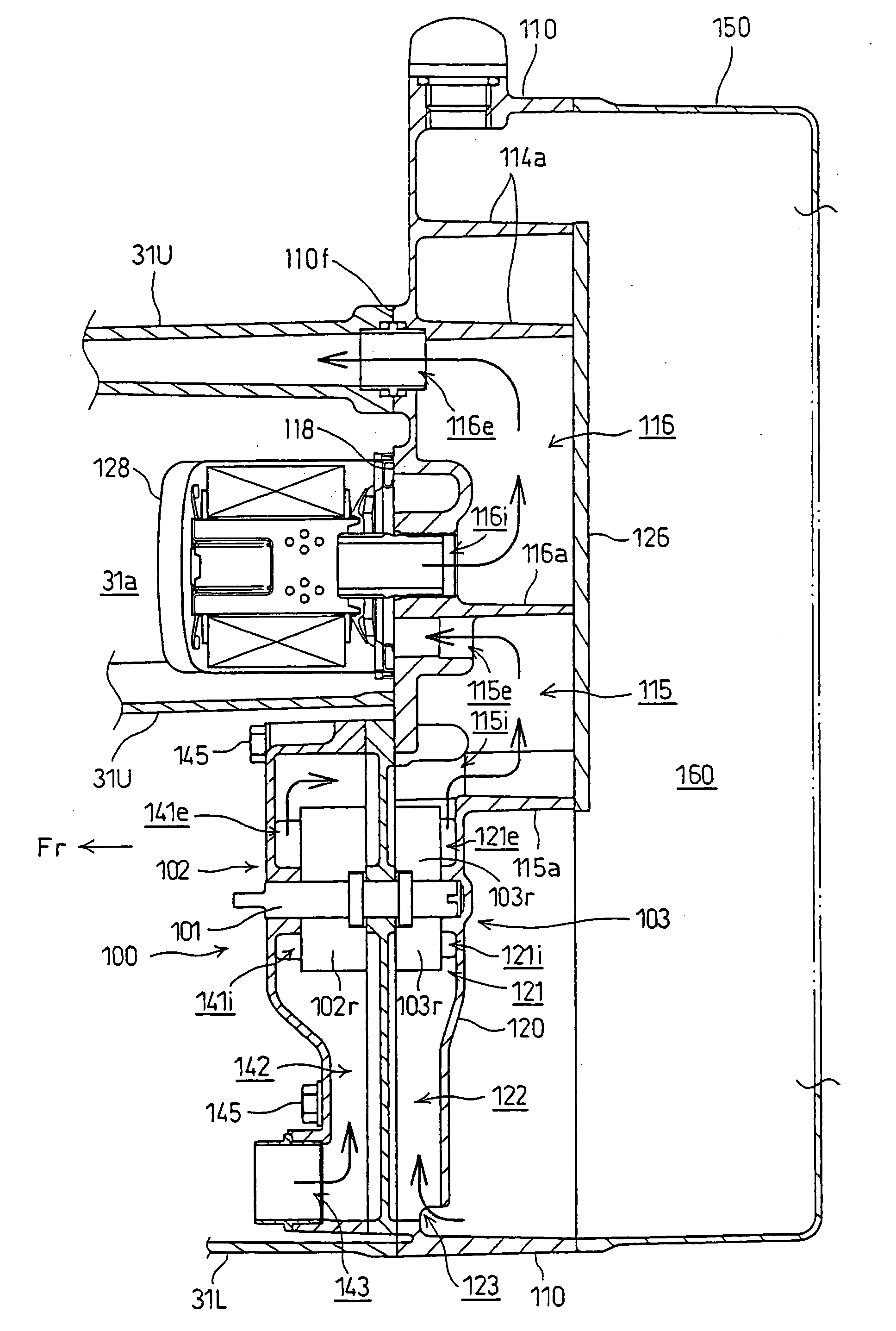
[0016]In the pump drive structure of a water-cooled internal combustion engine according to an embodiment of the present invention, the radiator is arranged forwardly of the internal combustion engine mounted on the vehicle vertically with the crankshaft oriented in the fore-and-aft direction. In addition, the water pump drive shaft is connected to the front end of the balancer shaft oriented in the fore-and-aft direction and the oil pump drive shaft is connected to the rear end thereof, so that the water pump and the radiator may be positioned closer. Thus, the water piping may be shortened.
[0017]Therefore, the total amount of water is reduced, and a weight reduction of the vehicle body is achieved.
[0018]Since the oil pump is arranged at the rear, the oil exhaustion or the air interfusion when climbing a slope may be prevented.
[0019]According to the pump drive structure of a water-cooled internal combustion engine according to an embodiment of the present invention, the oil strainer is disposed at the rear of the oil pan, and the oil channels are formed intensively in the rear of the crankcase. Therefore, the lengths of the oil channels may be shortened, and the total amount of oil is reduced, and the weight reduction of the vehicle body is achieved. At the same time, the oil exhaustion or the air interfusion when climbing a slope may be prevented.

Problems solved by technology

Thus, the number of shafts in the internal combustion engine is large.

Method used


Image

  • Pump drive structure of water-cooled internal combustion engine
  • Pump drive structure of water-cooled internal combustion engine
  • Pump drive structure of water-cooled internal combustion engine

Examples


Embodiment Construction

[0036]Referring now to FIG. 1 to FIG. 14, an embodiment of the present invention will be described.

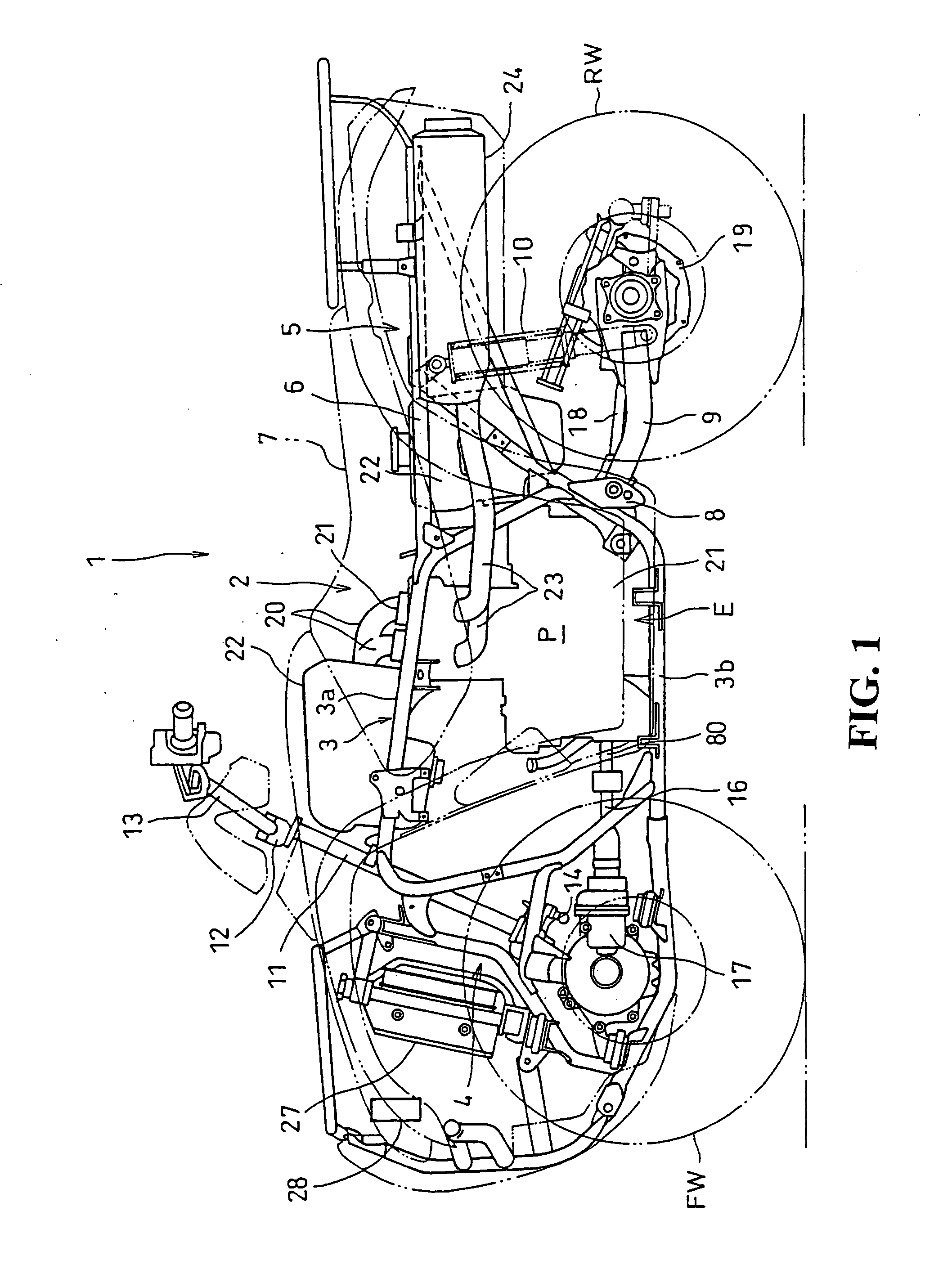
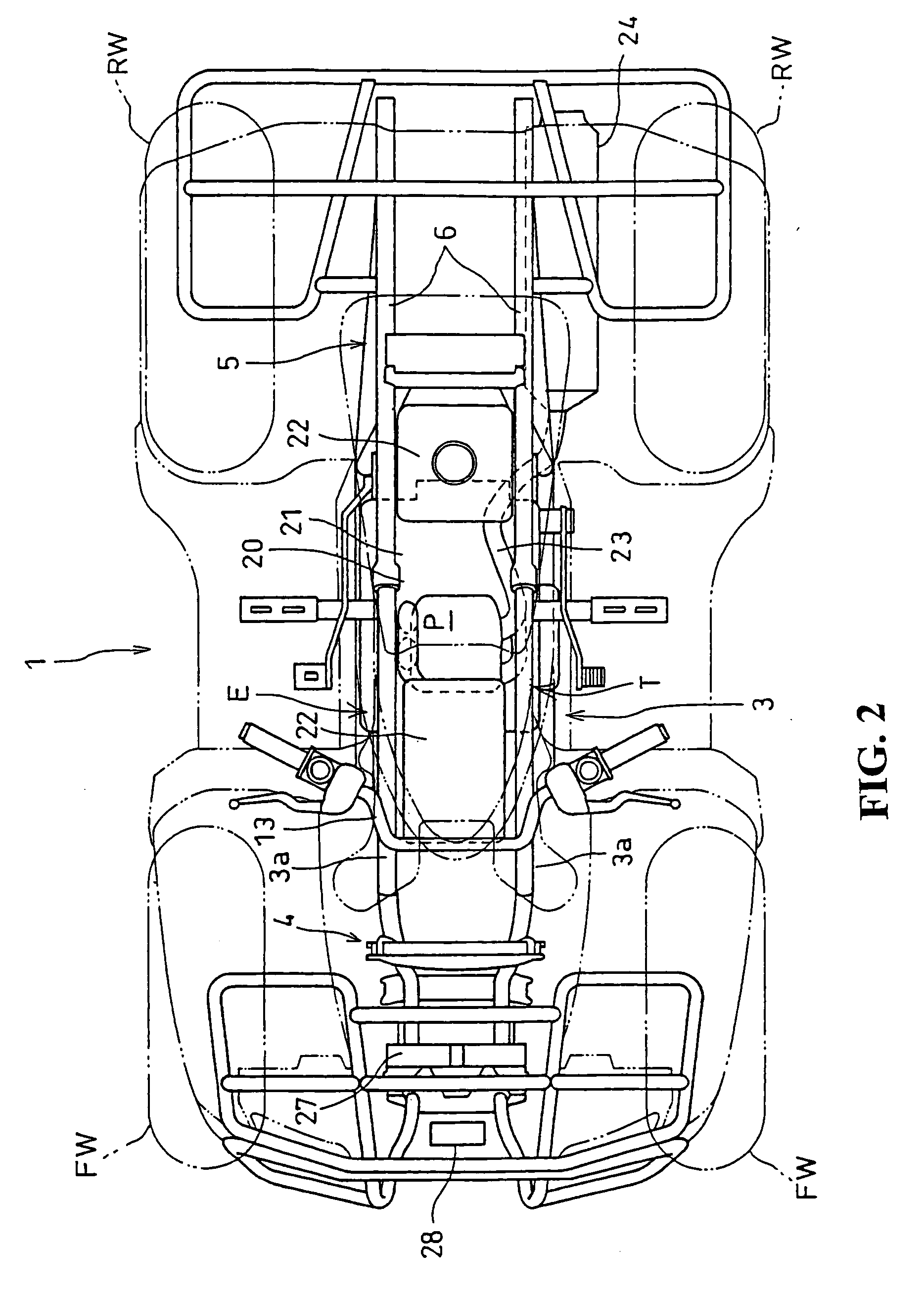
[0037]A side view of a rough-terrain traveling vehicle 1 is illustrated in a state wherein a vehicle body cover is removed. A water-cooled internal combustion engine E according to this embodiment is mounted is illustrated in FIG. 1 with a plan view of the same shown in FIG. 2.

[0038]In this embodiment, the front, rear, left and right are defined on the basis of a direction as viewed in the direction of travel of the vehicle.

[0039]The rough-terrain traveling vehicle 1 is a saddle type four-wheel vehicle with a pair of left and right front wheels FW with low-pressure balloon tires for rough-terrain being mounted thereon. A pair of left and right rear wheels RW are provided on which the same type of balloon tires are mounted to be suspended in the front and rear of a vehicle body frame 2.

[0040]The vehicle body frame 2 is configured with a plurality of types of wheel material joined togeth...


PUM


Abstract

To provide a pump drive structure for a water-cooled internal combustion engine in which the number of revolving shafts arranged in parallel in an internal combustion engine is reduced and a power transmission mechanism is eliminated. Thus, the internal combustion engine is downsized. The pump drive structure of a water-cooled internal combustion engine is provided in which a balancer shaft is arranged in parallel with a crankshaft at a position where crank webs of the crankshaft and balancer weights are overlapped in the axial direction. An oil pump drive shaft of an oil pump is connected coaxially at one end of the balancer shaft, and a water pump drive shaft of a water pump is connected coaxially with the other end of the balancer shaft.

Description

CROSS-REFERENCE TO RELATED APPLICATIONS[0001]The present application claims priority under 35 USC 119 to Japanese Patent Application No. 2006-246097 filed on Sep. 11, 2006 the entire contents of which are hereby incorporated by reference.BACKGROUND OF THE INVENTION[0002]1. Field of the Invention[0003]The present invention relates to a pump drive structure of a water pump and an oil pump in a water-cooled internal combustion engine.[0004]2. Description of Background Art[0005]A coaxial arrangement of the drive shafts of a water pump and an oil pump in a water-cooled internal combustion engine is generally employed, for example, as set forth in JP-A-2001-280111.[0006]The water-cooled internal combustion engine described in JP-A-2001-280111 is mounted laterally to a motorcycle with a crankshaft thereof oriented in the lateral width thereof.[0007]A pair of balancer shafts are arranged above and below the crankshaft with a pump drive shaft being arranged further below the lower balancer s...

Claims


Application Information

Patent Timeline
IPC IPC(8): F01M1/02F16F15/24
CPCF01M2001/0276F01M1/02
Inventor INUI, HIROATSUSUMI, HIROMI
Owner HONDA MOTOR CO LTD
Learn More