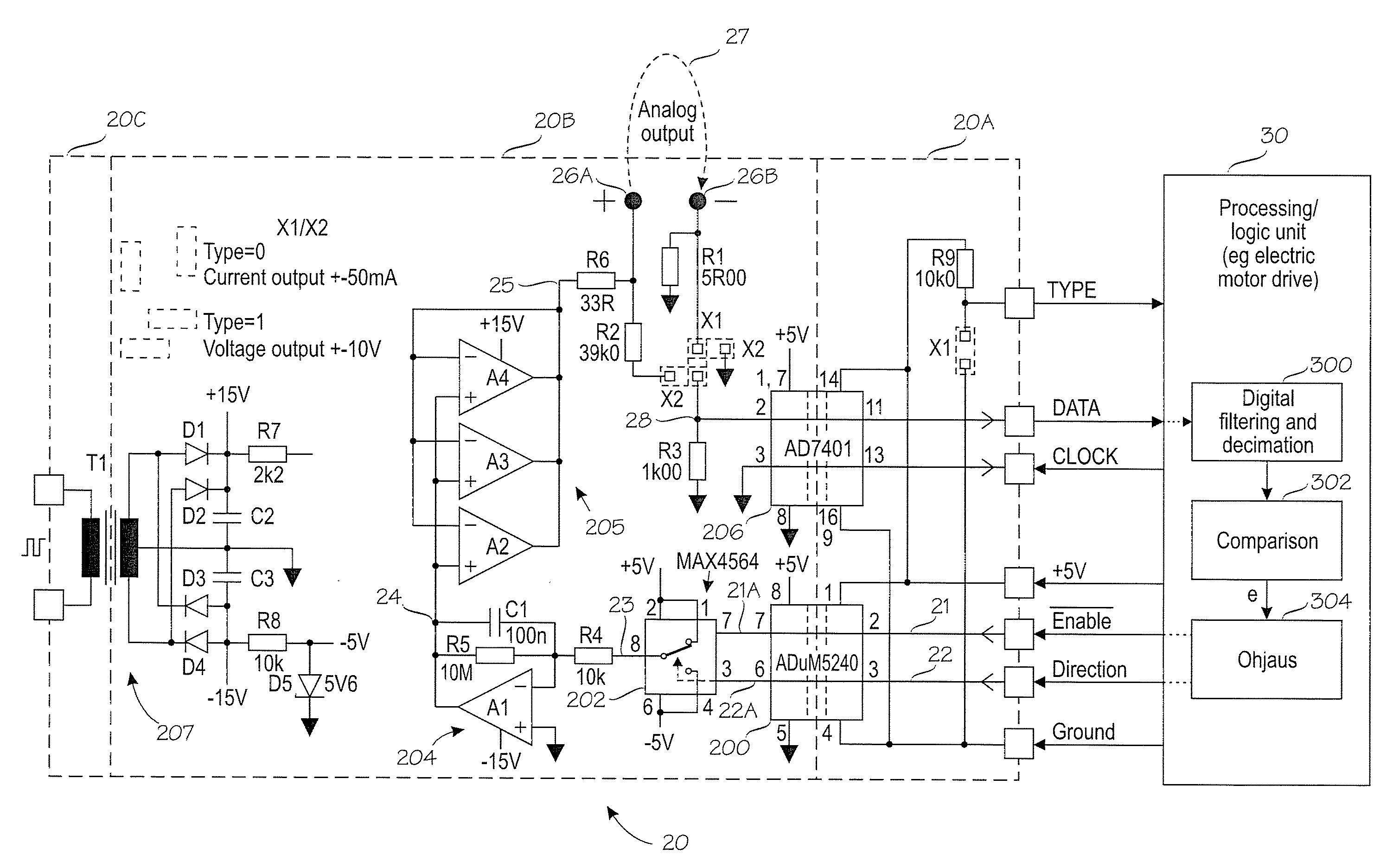
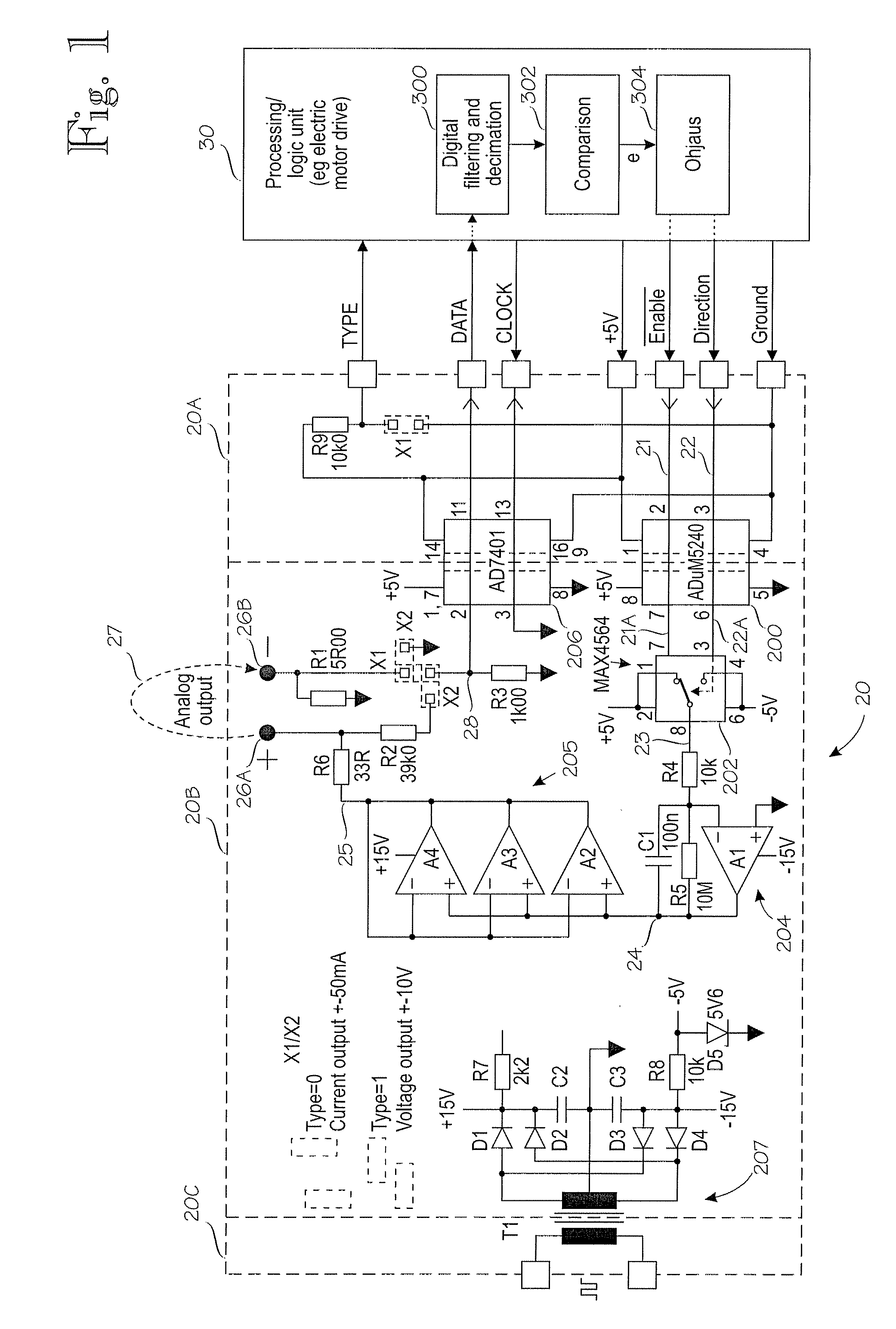
[0005]According to the invention, absolute values of output variables are measured and regulated continuously to ensure the
correctness of the signal. According to an embodiment, the actual current or voltage value of an analog output signal is measured and digitized, the difference between said digitized actual current or voltage value and a desired current or voltage value is determined, and the generation of the analog output signal is controlled with a
digital control signal in such a manner that said difference decreases. With the solution of the invention, the
absolute accuracy and stability of the analog output signal only depend on the accuracy of the measurement and digitizing. All errors of the circuit
branch generating the
analog signal are compensated through a
feedback loop, because if the output signal does not correspond to the command value, the generation of the analog output signal is immediately controlled with a
digital control signal to decrease said difference. With the invention, conversion from digital control to an analog output signal can be achieved using an inexpensive solution, because the accuracy of the conversion need not be set as strict requirements as before. Even though the invention requires measuring and digitizing the output signal, the device is still as a whole inexpensive, because an accurate A / D converter is considerably less expensive than an accurate D / A converter whose accuracy and stability is further reduced by the separate buffering required in the output. According to an embodiment of the invention, the digitizing of the measurement is performed with a sigma-
delta (Σ / Δ) modulator. A sigma-
delta modulator is, due to its mode of operation, particularly resistant to different interference peaks, and its
absolute accuracy and stability are excellent. In an embodiment of the invention, a digitized 1-bit signal generated by a sigma-
delta modulator is digitally filtered and decimated to obtain a multibit, digitized, actual current or voltage value.
[0006]In various embodiments of the invention, there is preferably galvanic separation between the analog output and digital control. This reduces interference and errors that propagate to points critical to the accuracy of the device. Galvanic separation also provides a safety feature in case a signal in network potential, for instance, was connected by accident the analog output connectors. In an embodiment of the invention, digitizing is performed using an analog-to-
digital conversion circuit, such as a sigma-delta modulator with integrated galvanic separation between the input and output. Correspondingly, a digital-to-analog conversion circuit with integrated galvanic separation between the input and output may be used in digital-to-analog conversion. Alternatively, it is possible to use separate galvanically separating circuits. In an embodiment of the invention, galvanic separation is implemented with an integrated DC-to-
DC converter. It is further possible to use in the circuit
branch (D / A) generating the voltage and the digitizing measuring
branch (A / D) galvanic separation methods that differ from each other. In various embodiments of the invention, the power source of the analog parts of the device may be galvanically separated from other operating voltages of the surrounding equipment, such as an
electric motor drive.
[0008]The device of the invention is intended primarily for use in measuring and
control signal transmitters. A particular field of application is
electric motor drives. In an
electric motor drive comprising a device of the invention, a circuit branch generating an analog output and a digitizing measuring branch are provided on a separate circuit board that is mounted in a circuit board connector on a main circuit board of the
motor drive, and the control means that receive a digitized measuring signal and generate a digital
control signal are provided on the main circuit board. With these solutions, it is possible to reduce the structural problems associated with traditional measuring and control signal transmitters.

