Test apparatus for determining performance degradation

a technology of performance degradation and test apparatus, applied in the field of testing apparatus, can solve the problems of difficult accurate grasping of characteristics and difficult accurate determination of gate voltage initial valu

Inactive Publication Date: 2008-07-24
EASTMAN KODAK CO
View PDF0 Cites 14 Cited by
  • Summary
  • Abstract
  • Description
  • Claims
  • Application Information

AI Technical Summary

Benefits of technology

[0007]The present invention provides a testing apparatus that tests performance degradation of a transistor to be tested, including: a stress application circuit that includes an operational amplifier, where an output terminal is connected to the gate of the transistor to be tested, a negative input terminal is connected to the source of the transistor to be tested, and a positive input terminal is connected to the output of a gate power source; a resistor that is connected between the negative input terminal and a negative power source, and causes flow, in the resistor, of the drain current flowing in the transistor to be tested, and a drain power source that supplies predetermined drain voltage to the drain of the trans

Problems solved by technology

The conventional method has a long response time from application of stress to a point where desired drain current is reached, and accurately determining the initial valu

Method used


Image

  • Test apparatus for determining performance degradation
  • Test apparatus for determining performance degradation
  • Test apparatus for determining performance degradation

Examples


Embodiment Construction

[0017]Hereinafter, the embodiment will be described with reference to the drawings.

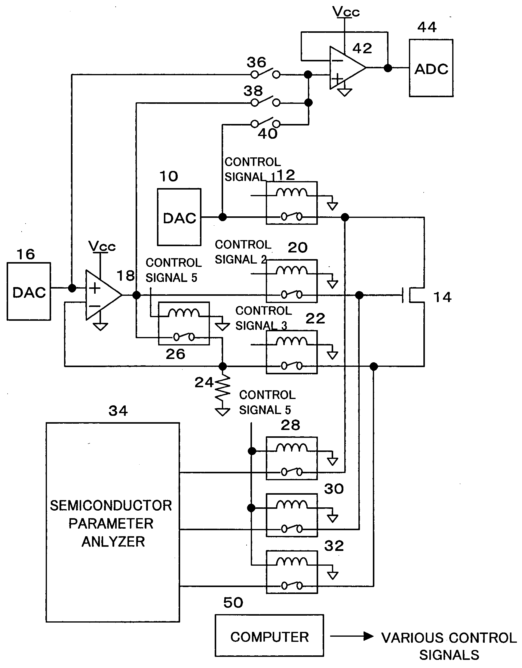
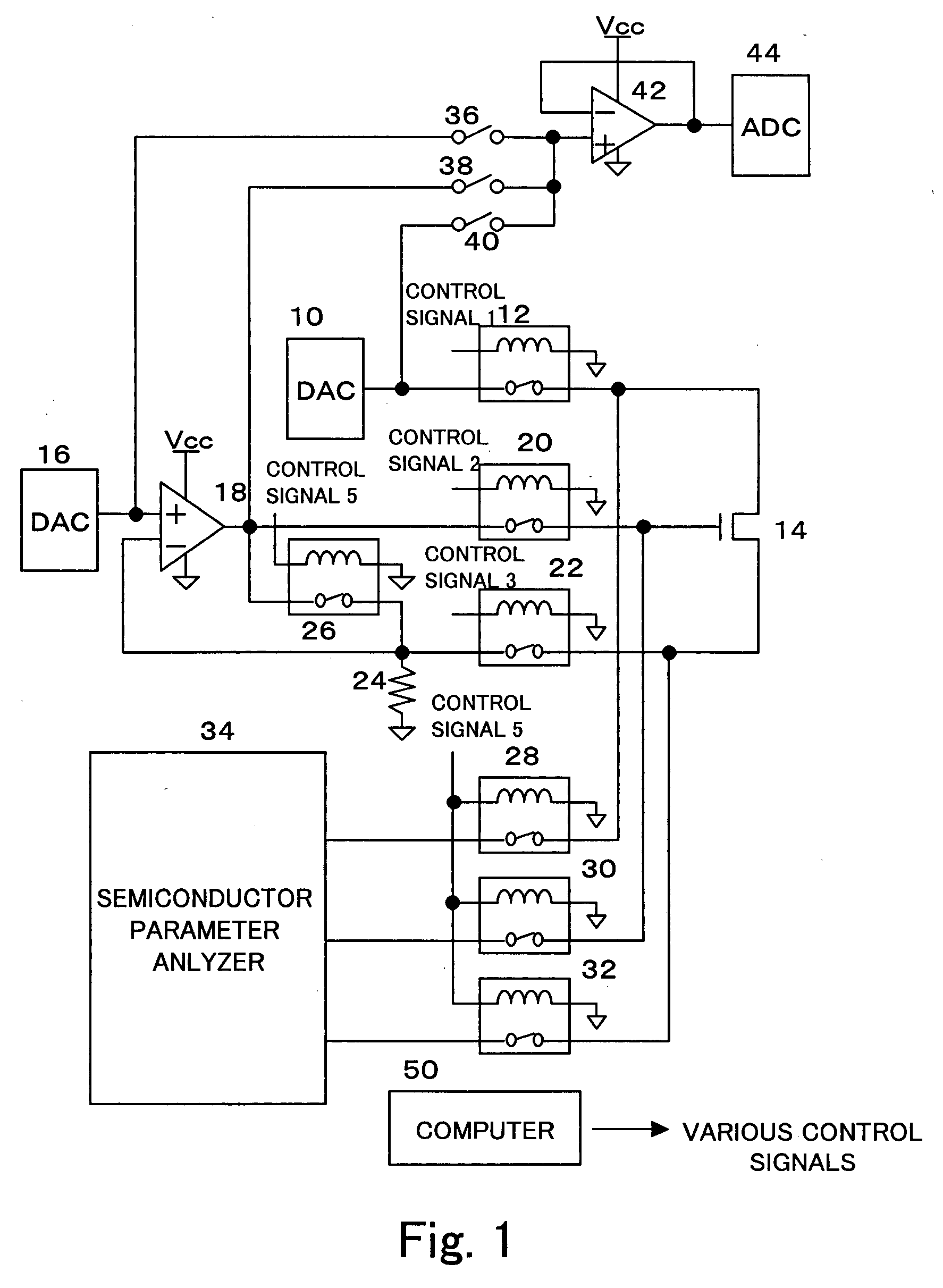
[0018]FIG. 1 shows the constitution of the testing apparatus according to the embodiment. The output terminal of a digital to analog converter (DAC) 10 that converts digital data into analog voltage is connected to the drain of an N-channel transistor to be tested 14, via a relay 12 that is turned ON / OFF by a control signal 1. Further, the output terminal of a DAC 16 is connected to the positive input terminal of an operational amplifier 18. The output terminal of the operational amplifier 18 is connected to the gate of the transistor to be tested 14 via a relay 20 that is turned ON / OFF by a control signal 2. The source of the transistor to be tested 14 is connected to the negative input terminal of the operational amplifier 18 via a relay 22 that is turned ON / OFF by a control signal 3, and the negative input terminal of the operational amplifier 18 is connected to the ground via a resistor 24.

[0019]T...


PUM


Abstract

Provided is a testing apparatus that accurately tests changes in threshold value of a transistor. The output of an operational amplifier is connected to the gate of a transistor to be tested, and the source of the transistor to be tested is negatively fed back to the negative input terminal of the operational amplifier. By applying desired voltage from a DAC to the positive input terminal of the operational amplifier, the operational amplifier operates so as to maintain a current flowing in the resistor at a constant value, thereby performing a test where the current flowing in the transistor to be tested is maintained at a constant value.

Description

CROSS-REFERENCE TO RELATED APPLICATION[0001]This application claims priority of Japanese Patent Application No. 2006-255063 filed Sep. 20, 2006 which is incorporated herein by reference in its entirety.FIELD OF THE INVENTION[0002]The present invention relates to a testing apparatus that tests characteristic changes due to the use of transistors.BACKGROUND OF THE INVENTION[0003]Conventionally, a liquid crystal display (LCD), an organic EL display (OLED display), or the like has employed an active matrix where elements for display control are provided for each pixel.[0004]For example, there exists an AMOLED display where amorphous silicon thin film transistors (a-Si:H TFT) are used as elements for driving the OLED element of each pixel. In the AMOLED, it is necessary to prevent abnormal display due to current changes, which are caused by the changes in drain current—gate voltage characteristics of a transistor with time. Therefore, the AMOLED display is preferably provided with a comp...

Claims


Application Information

Patent Timeline
IPC IPC(8): G01R31/26
CPCG01R31/2621G09G2300/08G09G3/006
Inventor MAEKAWA, YUICHI
Owner EASTMAN KODAK CO
Why Eureka
Try Eureka