
Liquid crystal display device and manufacturing method thereof

a technology of liquid crystal display and manufacturing method, which is applied in non-linear optics, instruments, optics, etc., can solve the problems of deteriorating the viewing angle performance of dark display, and achieve the effects of advanced image information, high picture quality, and high picture quality

Inactive Publication Date: 2008-07-24
HITACHI DISPLAYS
View PDF4 Cites 2 Cited by
  • Summary
  • Abstract
  • Description
  • Claims
  • Application Information

AI Technical Summary

Benefits of technology

[0024]An object of the invention is to provide a transflective liquid crystal display device which realizes a wide viewing angle similar to that in the transmissive IPS system by suppressing deterioration of the transflective display characteristics by forming the retardation layer so as to fall within the tolerance range of the designed pattern with respect to the reflective display unit.
[0035]According to the present invention, the display with high picture quality similar to that of a monitor can be carried. If it is used as a display of a cellular phone, image information of high picture quality can be reconstructed and the more advanced image information can be handled. Further, if it is used for a digital camera, an image before photographing and the photographed image can be easily confirmed. It is also presumed that a receiving state of a portable television will be remarkably improved in future in association with the spread of terrestrial digital broadcasting. If it is used for a portable television, the image information of high picture quality can be reproduced in any place.

Problems solved by technology

However, since the surplus phase difference occurs in the viewing angle direction since the retardation plates exist between the liquid crystal layer and the polarizers, the viewing angle performance of the dark display deteriorates.

Method used


Image

  • Liquid crystal display device and manufacturing method thereof
  • Liquid crystal display device and manufacturing method thereof
  • Liquid crystal display device and manufacturing method thereof

Examples


embodiment 1

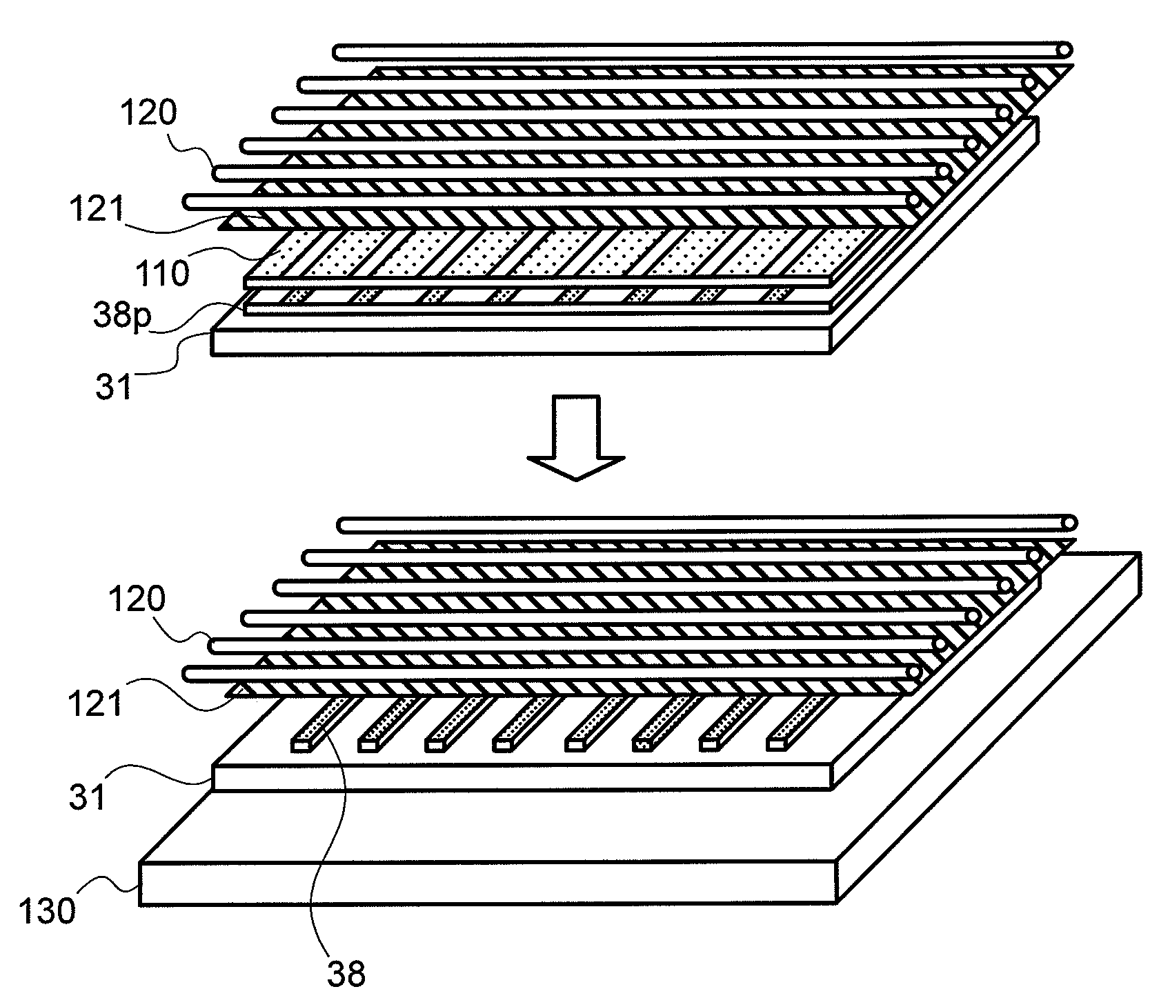
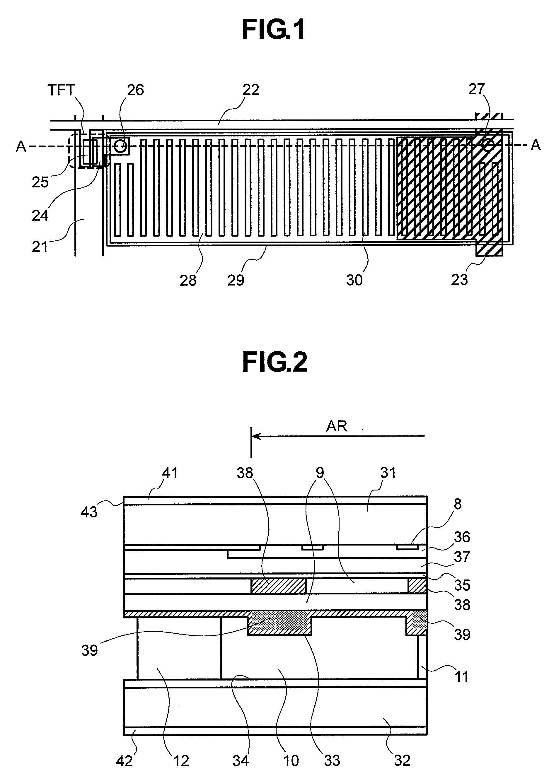
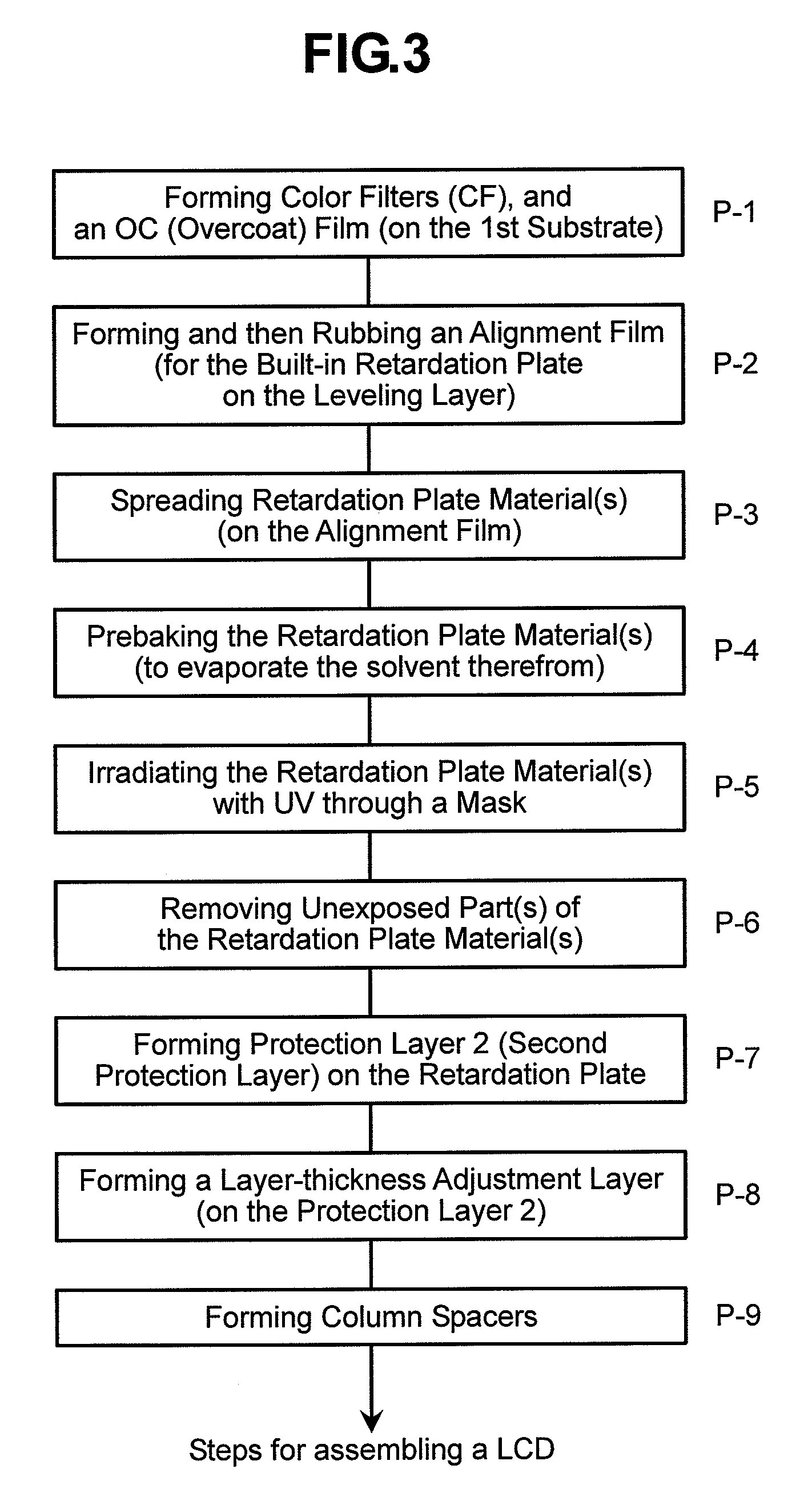
[0045]FIG. 1 is a plan view for illustrating a constitutional example of a pixel of a liquid crystal panel constituting Embodiment 1 of the liquid crystal display device according to the present invention. FIG. 2 is a cross-sectional view of FIG. 1 taken along line A-A′ for illustrating a schematic constitutional example of a pixel of the liquid crystal panel shown in FIG. 1. In FIG. 2, to simplify illustration, a thin film transistor, pixel electrode, common electrode and second polarizer which are provided on the second substrate are not shown. The liquid crystal panel of Embodiment 1 is constituted by a first substrate 31, a liquid crystal layer 10 and the second substrate 32, and the liquid crystal layer 10 is nipped in a gap between the first substrate 31 and second substrate 32 opposing each other. The first substrate 31 has, on its main face (inner face), a color filter 36 and a levelling layer (first protective film) 37 demarcated by a black matrix 8, a third alignment film ...

embodiment 2

[0084]Embodiment 2 has a construction similar to FIG. 1 except that the third alignment film 35 in Embodiment 1 is formed on the entire first substrate 31 including the seal area, and therefore no repeated explanation will be provided.

[0085]Examples of photopolymerization initiators contained in conventional retardation layer-forming materials include IRUGACURE® 907, IRUGACURE 369, IRUGACURE 819, IRUGACURE 127, DAROCUR® TPO, IRUGACURE OXE01, 2-(3,4-methylenedioxyphenyl)-4, and 6-bis(trichloromethyl)-1,3,5-triazine manufactured by Ciba Specialty Chemicals, among others. Examples of photopolymerization initiators are shown in “Chemical formula 3”.

[0086]When a photopolymerization initiator selected from the above is added, the polymerization speed is high, and the degree of polymerization is presumed to be high. Therefore, the pattern undergoes excessive curing exceeding the width (size) of the mask opening in pattern exposure, and the pattern width after development becomes about 10 t...


PUM

PropertyMeasurementUnit
angleaaaaaaaaaa
angleaaaaaaaaaa
thicknessaaaaaaaaaa

Abstract

In the present invention, to realize a liquid crystal display device of high-definition transflective IPS system comprising an inner retardation plate (retardation layer) in a reflective display unit, the retardation layer is formed of liquid crystal monomers with acrylates containing a polymerization initiator and either one or both of a triplet quencher and a radical quencher added.

Description

[0001]The present application claims priority from Japanese application JP2007-000963 filed on Jan. 9, 2007, the content of which is hereby incorporated by reference into this application.BACKGROUND OF THE INVENTION[0002]1. Field of the Invention[0003]The invention relates to a liquid crystal display device, particularly to a liquid crystal display device which can made reflective display of images in a wide range of environment from a light place to a dark place and execute a transmissive display with a wide viewing angle and high picture quality, and to a method of manufacturing the same.[0004]2. Description of the Related Art[0005]At present, a transmissive liquid crystal display device with a wide viewing angle of an IPS (In Plane Switching) system, a VA (Vertical Alignment) system, or the like has been spread as a monitor used for various devices and is also used as a television by improving response performance. A liquid crystal display device has also been spread to the field...

Claims


Application Information

Patent Timeline
Patent Type & Authority Applications(United States)
IPC IPC(8): G02F1/1335
CPCG02F1/133632G02F2413/09G02F2001/133565G02F1/134363G02F1/133565G02F1/133631
Inventor SANO, YASUSHISEKIGUCHI, SHINJITAKANOSU, KEIJIHARA, KOJIMATSUURA, HIROYASU
Owner HITACHI DISPLAYS
Learn More