Color Measuring head and Scanner Device Equipped Therewith

a color measuring head and scanner technology, applied in the field of scanner devices, can solve the problems of not being able to rule out the possibility of the measuring optics becoming dirty, affecting the accuracy of the measurement, and requiring a more complex design of the measuring optics than is available in the prior art, and achieves the effect of high accuracy

Active Publication Date: 2008-07-24
X RITE SWITZERLAND
View PDF16 Cites 16 Cited by
  • Summary
  • Abstract
  • Description
  • Claims
  • Application Information

AI Technical Summary

Benefits of technology

[0021]It is an objective of this invention to improve a color measuring head and a corresponding scanner device of the generic type equipped with a color measuring head so that they satisfy the demands explained above placed on a modern, high-precision and fast scanning system and in particular are suitable for taking highly accurate measurements of even the smallest measurement fields without contact.

Problems solved by technology

Measuring small measurement fields cleanly at a high scanning speed requires a more complex design of measuring optics than is available in the prior art.
There is no way of ruling out the possibility of the measuring optics becoming dirty over the course of time.
Dirt exacerbates the problems associated with the high density measuring range and cross-talk.
Fast-scanning spectral color measuring systems incorporating polarization filter technology are not yet available on the market.
The scanning measuring systems known to date do not satisfy the requirements outlined above or satisfy only some of them or do so only to an unsatisfactory degree.
Taking measurements based on a time sequence involving a lot of spectral channels limits the minimum measuring time which can be achieved, which restricts the maximum scanning speed and the minimum measurement field size.
This positional offset may lead to fluctuations in the measurement values in the case of grid-patterned fields and a small measuring speckle.
On the one hand, the fact of providing two spectral analysis systems in the collection channel leads to additional costs.
On the other hand, a complete spectral measurement is not available using polarization filters.

Method used


Image

  • Color Measuring head and Scanner Device Equipped Therewith
  • Color Measuring head and Scanner Device Equipped Therewith
  • Color Measuring head and Scanner Device Equipped Therewith

Examples


Embodiment Construction

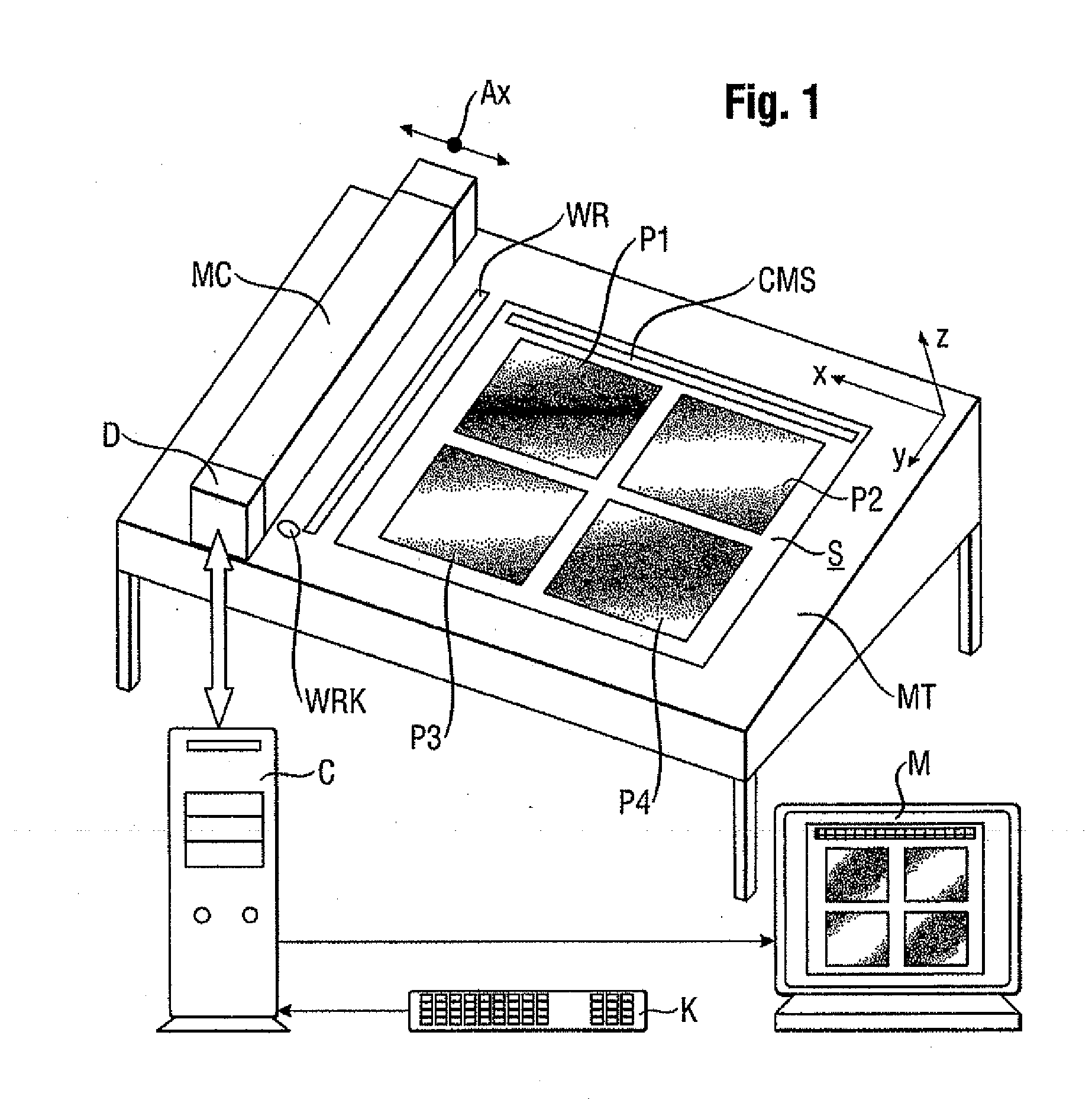
[0038]In terms of its general construction, the scanner device proposed by the invention conforms to standard measuring apparatus, of the type typically used in the graphics industry for taking photoelectric measurements of printed sheets taken from a printing process on the basis of pixels, for example. The scanner device comprises a sub-structure in the form of a measuring table MT with what is usually an inclined rectangular surface, on which the measured object S—the printed sheet to be measured—can be positioned. The measuring table therefore provides a support surface for the measured object. The printed sheet S typically contains a few (in this instance four, for example) graphic images P1-P4 and a (or several) color measuring strips CMS. In order to position the measured object S, stops are provided on the measuring table MT, although these are not illustrated. The measured object S is preferably secured on the measuring table MT by electrostatic means or by means of known s...


PUM


Abstract

A scanner device includes a support surface for the measured object and a drive unit for moving a color measuring head across the support surface in at least one dimension thereof and for adjusting the height of the color measuring head in the direction perpendicular to the support surface, as well as a measuring and drive control unit activating the drive unit and cooperating with the color measuring head (MH). The color measuring head (MH) is equipped with at least an illuminating channel (IC) and a collection channel (CC). The illuminating channel (IC) has a light source (10) and optical means (12-22) for illuminating the measured object (S) at a measurement site at a mean angle of incidence of 45 E. The collection channel (CC) has optical means (24-34) for capturing the light emanating from the measured object at the measurement site at a mean collection angle of 0 E and coupling it into a light guide (LF), which directs the captured measurement light to a wavelength-selective photoelectric transformer preferably provided in the form of a spectrometer, which resolves it into a number of wavelength ranges and generates an electric measurement signal corresponding to each wavelength range. The color measuring head is suitable for taking high-precision measurements of even the smallest measurement fields without contact.

Description

BACKGROUND OF THE INVENTION[0001]The invention relates to a scanner device of the type for measuring the color properties of a measured object pixel by pixel by means of a color measuring head, which scanner device is able to move the color measuring head in at least one dimension across a measurement object to be measured, and the color measuring head has at least one illuminating channel and a collection channel, which illuminating channel has a light source and optical means for illuminating the measured object at a measurement site at a mean angle of incidence of 45°, and which collection channel has optical means for capturing measurement light emitted from the measured object at the measurement site at a mean collection angle of 0° and coupling it into a light guide which directs the captured measurement light to a wavelength-selective photoelectric transformer, preferably provided in the form of a spectrometer which resolves it into a number of wavelength ranges and generates...

Claims


Application Information

Patent Timeline
Patent Type & Authority Applications(United States)
IPC IPC(8): G01J3/00G01J4/00G01J3/447
CPCG01J3/02H04N1/00058G01J3/0213G01J3/024G01J3/027G01J3/0278G01J3/50G01J3/501H04N1/00005H04N1/00015H04N1/00023H04N1/00045H04N1/00047H04N1/0005G01J3/0208
Inventor EHBETS, PETERKOHLBRENNER, ADRIAN
Owner X RITE SWITZERLAND
Why Eureka
Try Eureka