Image forming apparatus

a technology of forming apparatus and forming chamber, which is applied in the field of image forming apparatus, can solve the problems of giving a problem in image quality, increasing the cost of the other side, and reducing so as to reduce the size of the apparatus and remove the noise of speckles

Inactive Publication Date: 2008-07-24
PANASONIC CORP
View PDF2 Cites 4 Cited by
  • Summary
  • Abstract
  • Description
  • Claims
  • Application Information

AI Technical Summary

Benefits of technology

[0009]With the image forming apparatus configured as above, it is possible to achieve a significant reduction of the apparatus size by the layout in which the extension of the rotation axis of the polygonal mirror that scans laser beams from the plural laser light sources passes through the multiplexing member. Further, by scanning plural laser beams by a single polygonal mirror, it is possible to remove speckle noises caused by plural laser beams efficiently without interfering with a reduction of the apparatus size.

Problems solved by technology

In addition, in a case where lasers are used as the light sources, speckle noises, which give a problem in image quality, are known to occur.
However, JP-A-2005-99160 achieves a reduction of the apparatus size by making the lasers compact on one hand, but it has a problem that the cost is increased on the other.
Further, because JP-A-11-64789 removes the speckle noises by providing the configuration to remove speckle noises separately for each of the R, G, and B light sources, it has a problem that the apparatus size is undesirably increased.

Method used


Image

  • Image forming apparatus
  • Image forming apparatus
  • Image forming apparatus

Examples


first embodiment

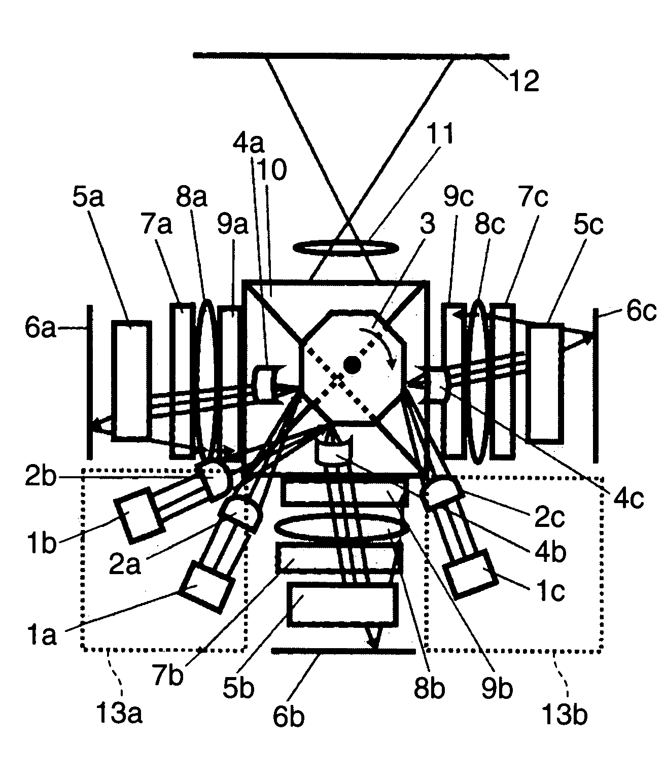
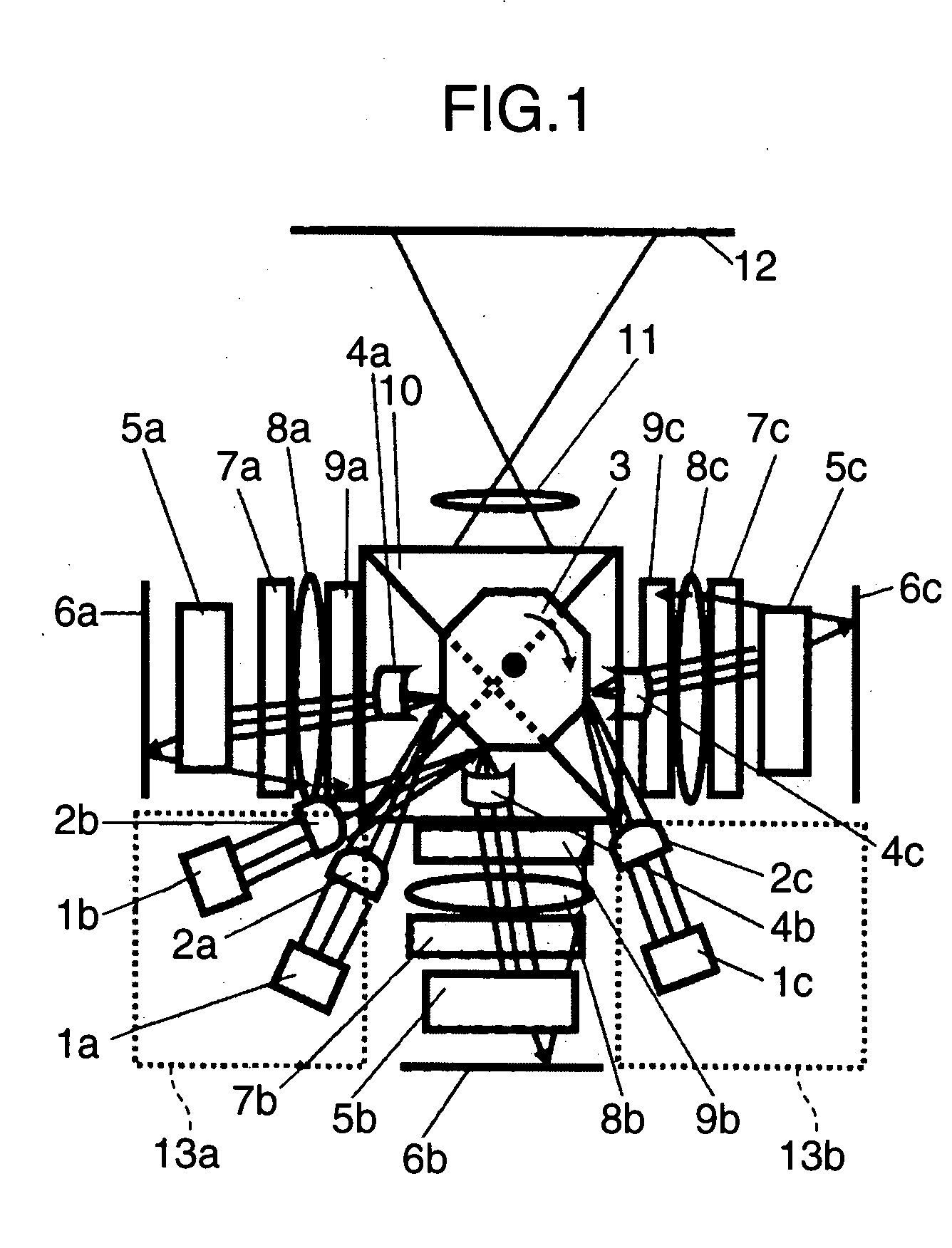
[0019]FIG. 1 is a top view schematically showing the configuration of an image forming apparatus according to a first embodiment of the invention. FIG. 2 is a side view of the image forming apparatus. Hereinafter, a mechanism for operations of the image forming apparatus of this embodiment will be described using FIG. 1 and FIG. 2. The optical system in the image forming apparatus of this embodiment is provided with plural laser light sources including a B light source 1a, a G light source 1b, and an R light source 1c, cylindrical lenses 2a, 2b, and 2c corresponding to the B light source 1a, the G light source 1b, and the R light source 1c, respectively, a polygonal mirror 3, cylindrical lenses 4a, 4b, and 4c, cylindrical mirror arrays 5a, 5b, and 5c, mirrors 6a, 6b, and 6c, diffusers 7a, 7b, and 7c, field lenses 8a, 8b, and 8c, spatial light modulators 9a, 9b, and 9c, and a multiplexing member 10. As with the cylindrical lenses 2a, 2b, and 2c, the cylindrical lenses 4a, 4b, and 4c,...

second embodiment

[0037]A second embodiment of the invention will now be described. This embodiment is configured to achieve a releasing mechanism by a simple configuration in the image forming apparatus of the first embodiment above. FIG. 4 is a side view schematically showing the configuration of an image forming apparatus of this embodiment.

[0038]When an image forming apparatus, such as a projector, is reduced in size, it is normal that the surface area of the apparatus becomes smaller, which makes it important to release heat inside the apparatus. Additionally providing a fan for this purpose, however, is contrary to a reduction in size.

[0039]For this purpose, as is shown in FIG. 4, the image forming apparatus of this embedment is further provided with a fan 18 attached to the polygonal mirror 3. The fan 18 rotates at a high speed integrally with the polygonal mirror 3 and creates a current of air by rotating at a high speed for releasing heat generated inside the apparatus to outside the apparat...

third embodiment

[0040]A third embodiment of the invention will now be described. This embodiment is configured to remove speckle noises using optical face tangle errors occurring in the reflection surfaces of the polygonal mirror in the image forming apparatus of the first and second embodiments above. FIG. 5 is an enlarged side view of a polygonal mirror used in an image forming apparatus of this embodiment. Hereinafter, a method of removing speckle noises using optical face tangle errors of the polygonal mirror 3 will be described using FIG. 5.

[0041]As is shown in FIG. 5, the polygonal mirror 3 is processed in the fabrication sequence so that the reflection surfaces and the rotation axis become almost parallel to each other. However, it is normal that minor tangle errors occur in the reflection surfaces. For example, a reflection surface 19a is almost parallel to the rotation axis, whereas a downward tangle error occurs in a reflection surface 19b and an upward tangle error occurs in a reflection...


PUM


Abstract

An image forming apparatus includes plural laser light sources, a polygonal mirror that scans plural laser beams from the plural laser light sources, and a multiplexing member that combines the plural laser beams scanned by the polygonal mirror. The polygonal mirror is disposed above or below the multiplexing member, and the extension of the rotation axis of the polygonal mirror passes through the multiplexing member. When configured in this manner, it is possible to reduce the apparatus size and speckle noises caused by the plural laser beams.

Description

BACKGROUND OF THE INVENTION[0001]1. Field of the Invention[0002]The present invention relates to an image forming apparatus, such as a projector, that uses light sources for plural colors including red (R), green (G), and blue (B).[0003]2. Background Art[0004]A display, such as a projector that projects an image onto a screen, has been known. The main stream has been a type using a high pressure mercury-vapor lamp as the light source. However, a laser display using a laser as the light source is being studied in recent years. Using red (R), green (G), and blue (B) lasers as the light sources is advantageous in many respects, for example, a color reproducible range is broadened markedly to the extent that color representation close to original colors is enabled and low power consumption can be achieved.[0005]Of the needs for a projector, one need is to reduce the projector to a portable size so as to be carried around. In addition, in a case where lasers are used as the light sources...

Claims


Application Information

Patent Timeline
Patent Type & Authority Applications(United States)
IPC IPC(8): G02B26/08
CPCG02B27/1006G02B26/123
Inventor SHIKII, SHINICHIFURUYA, HIROYUKIMIZUUCHI, KIMINORIITOH, TATSUOMIZUSHIMA, TETSURO
Owner PANASONIC CORP
Why Eureka
Try Eureka