Two-Channel Method For Continuously Determining at Least One Output Signal From Changing Input Signals

a two-channel method and input signal technology, applied in the field of signal evaluation, can solve the problems of two different chips, two different chips, and very high interference risk of cited electronic circuitry

Inactive Publication Date: 2008-07-24
SIEMENS AG
View PDF5 Cites 14 Cited by
  • Summary
  • Abstract
  • Description
  • Claims
  • Application Information

AI Technical Summary

Benefits of technology

[0011]An object of the invention is to provide a compact solution for allowing the transmitter signals to be processed on one silicon chip while at the same time allowing the security of both channels' monitoring to be insured.
[0013]The invention is based on the knowledge that although there have to be two different channels, only a single output signal is ever required. The output signal can hence in each case be produced in one channel and a check performed in the other to determine whether it is operating correctly. As that takesplace in alternation, in changeover mode (using a multiplexer), the result is high speed in determining errors in one of the channels.

Problems solved by technology

The cited electronic circuitry is, though, very interference-prone.
Because the position controller will no longer be able to operate reliably, the entire machine will be stopped.
The consequences of providing two different chips are high costs and large space requirements.
Although a possibility, the solution em-ploying a silicon trench is uneconomical because the trench width will need to accord with the specific ambient tempera-ture range.
For applications having high permissible ambient temperatures the silicon surface will accordingly in-crease uneconomically as its portion of the trench.

Method used


Image

  • Two-Channel Method For Continuously Determining at Least One Output Signal From Changing Input Signals
  • Two-Channel Method For Continuously Determining at Least One Output Signal From Changing Input Signals

Examples


Embodiment Construction

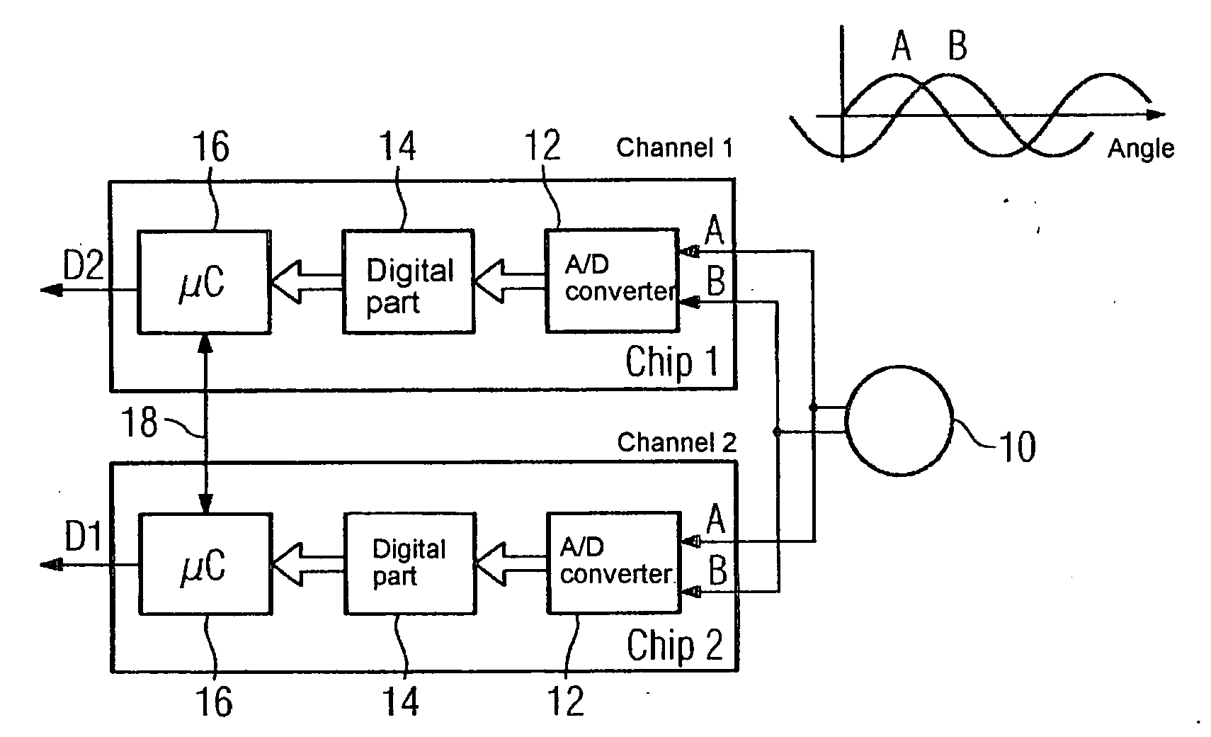
[0027]A transmitter 10, which can be an optical or a magnetic transmitter, feeds out the sinusoidal signal A and the cosinusoidal signal B as input signals for two channels on two different chips. In each chip an analog-to-digital converter 12 converts the analog signals into digital signals. The signal is further evaluated in a digital part 14 and a downstream microcomputer 16. The number of zero crossings of the sine stands therein for the extent of the rotation of the motor which the transmitter system is observing, and for fine measuring the precise angle of the input signal is determined by calculating the tangential arc from the ratio of the signal A to the signal B. The two microcomputers 16 feed out signals D1 and D2 each representing the position of a tool or work piece. The two signals D1 and D2 are mutually compared via a connecting lead 18, with the comparison preferably being able to take place in both microcomputers 16. If the values D1 and D2 diverge too much, then an...


PUM


Abstract

There is described a two-channel method for determining at least one output signal from variable input signals of sent by a transmitter, using two independent channels and consisting in alternately guiding the in put signals to said channels, wherein a multiplexer is used for switching said channels. A microprocessor contained in said channels delivers input test signals transmitted to the channel not currently receiving any variable input signal. Said channel transmits output signals compared with an expected value in order to verify the channel correct operation. Simultaneously, the other channel produces an output signal. Afterwards, the multiplexer switches a control signal.

Description

CROSS REFERENCE TO RELATED APPLICATIONS[0001]This application is the US National Stage of International Application No. PCT / EP2006 / 060604, filed Mar. 9, 2006 and claims the benefit thereof. The International Application claims the benefits of German application No. 10 2005 011 406.7 DE filed Mar. 11, 2005, both of the applications are incorporated by reference herein in their entirety.FIELD OF INVENTION[0002]The present invention relates to the evaluation of signals of the kind fed out by optical or magnetic transmitter systems that can be attached to motors on a machine tool.[0003]The invention relates also to an integrated circuit for evaluating the signals from the transmitter system and to a transmitter system of said type together with an integrated circuit.BACKGROUND OF INVENTION[0004]The present invention belongs to the domain “safety in the technical drive and control system for, for instance, machine tools”. A motor serves in a machine tool inter alia to change a tool's pos...

Claims


Application Information

Patent Timeline
Patent Type & Authority Applications(United States)
IPC IPC(8): G01D5/245H04B1/16
CPCG01D5/24461H03M1/303H03M1/1071H03M1/1004
Inventor KUHN, ANDREASSCHWESIG, GUNTER
Owner SIEMENS AG
Why Eureka
Try Eureka