System and method for precise beam positioning in ocular surgery

a laser and beam positioning technology, applied in the field of computer controlled laser surgical systems, can solve the problem that all of this cannot be done by merely an external examination of the eye, and achieve the effect of reducing the risk of complications and improving the safety of patients

Active Publication Date: 2008-07-24
TECHNOLAS PERFECT VISION
View PDF22 Cites 43 Cited by
  • Summary
  • Abstract
  • Description
  • Claims
  • Application Information

AI Technical Summary

Benefits of technology

[0008]A computer (i.e. a data processor) is electronically connected to both the beam delivery system and to the optical detector. With these connections, the computer is able to compare the location of desired focal points in the treatment area (based on pre-planned data for the surgery) with actual focal points. Deviations of actual focal points from desired focal points (i.e. error signals) can thus be identified. Using well known closed loop feedback control techniques, the delivery system is then adjusted to nullify or minimize the error signals. Consequently the system can be controlled to have its focal point follow a predetermined path through the treatment area. Alternatively, the system can be operated in an open-loop mode. If so operated, the focal point is moved to follow the predetermined path through the treatment area without any further adjustments. In the open-loop mode, however, it is still important to use the optical detector to establish an appropriate start point for the path of the focal point.
[0009]As indicated above, an important aspect of the present invention is its use of the optical detector to generate cross-sectional views of the treatment area. As envisioned for the present invention, such views can be sequentially made in real time. Further, they can be made from different perspectives, based on different cross-section planes through the eye. With these capabilities, the cross-sectional views can be used for control of the system, and they can also provide the operator with a three dimensional visualization of the treatment area. With this capability, it is envisioned that manual control over movements of the focal point in the treatment area is possible for the present invention. When used, manual control may either augment the computer control mentioned above, or provide an alternative to the computer control.

Problems solved by technology

All of this, of course, cannot be done by merely an external examination of the eye.

Method used


Image

  • System and method for precise beam positioning in ocular surgery
  • System and method for precise beam positioning in ocular surgery

Examples


Embodiment Construction

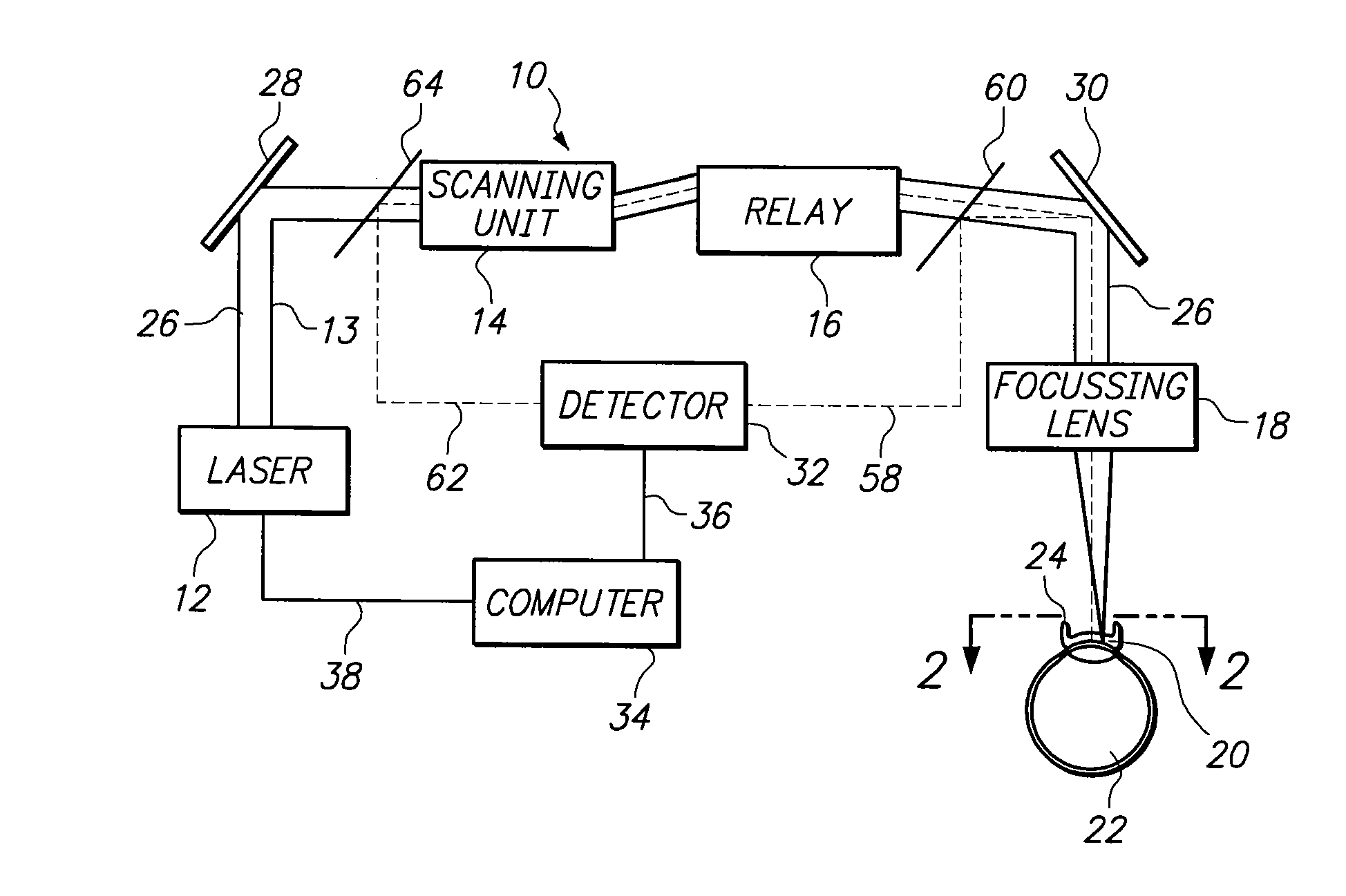
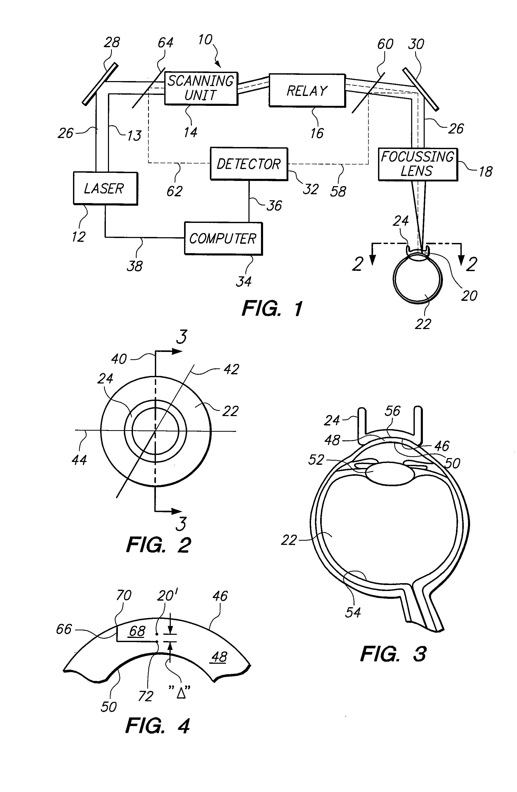
[0015]Referring initially to FIG. 1, an apparatus for performing ocular surgery in accordance with the present invention is shown and is generally designated 10. As shown, the apparatus 10 includes a laser source 12 for generating a surgical laser beam 13. For the present invention, the surgical laser beam 13 preferably includes a sequence of femtosecond pulses having a wavelength of approximately one thousand nanometers (λs=1,000 nm). FIG. 1 also implies that the apparatus 10 includes a scanning unit 14 that will allow the surgical laser beam 13 to be moved in orthogonal x, y and z directions. Relay optics 16 transfer the surgical laser beam 13 in a manner well known in the pertinent art, and a focusing lens 18 is used to focus the surgical laser beam 13 to a focal point 20.

[0016]As indicated in FIG. 1, the focal point 20 may be selectively established in the tissue of a patient's eye 22. A contact lens 24 that is mounted on the apparatus 10 by way of connections (not shown) is als...


PUM


Abstract

A system and method for ocular surgery includes a delivery system for generating and guiding a surgical laser beam to a focal point in a treatment area of an eye. Additionally, a contact device is employed for using the eye to establish a reference datum. Further, an optical detector is coupled to the beam path of the surgical laser to create a sequence of cross-sectional images. Each image visualizes both the reference datum and the focal point. Operationally, a computer then uses these images to position and move the focal point in the treatment area relative to the reference datum for surgery.

Description

FIELD OF THE INVENTION[0001]The present invention pertains generally to systems and methods for performing ocular surgery. More particularly, the present invention pertains to computer-controlled laser surgical systems. The present invention is particularly, but not exclusively, useful as a system and a method that incorporate optical coherence tomography (OCT) techniques for the purpose of imaging both a treatment area and a reference datum, to control laser beam focal point movements within the treatment area during a surgical operation.BACKGROUND OF THE INVENTION[0002]When using a laser beam to perform ocular surgery, the precise movement of the laser beam's focal point through the tissue to be altered is absolutely imperative. Specifically, focal point position accuracies within about ten microns (10 μm) are preferable. To do this, the desired path for the laser beam's focal point must have a precisely defined start point. And, the laser beam's focal point must then be moved alo...

Claims


Application Information

Patent Timeline
Patent Type & Authority Applications(United States)
IPC IPC(8): A61F9/008
CPCA61B5/0066A61F9/008A61F2009/00851A61F2009/00844A61F2009/00872A61F9/00825A61F9/009A61B3/113
Inventor LOESEL, FRIEDERGLASMACHER, MATHIASPAPE, ULRICH VON
Owner TECHNOLAS PERFECT VISION
Why Eureka
Try Eureka