
Ion beam apparatus having plasma sheath controller

a technology of plasma sheath controller and ion beam apparatus, which is applied in the field of plasma apparatus, can solve the problems of not being able to obtain high ion beam ion flux, and still being required for ion beam apparatus capable of increasing ion flux, and achieves high ion flux

Inactive Publication Date: 2008-07-31
SAMSUNG ELECTRONICS CO LTD
View PDF7 Cites 53 Cited by
  • Summary
  • Abstract
  • Description
  • Claims
  • Application Information

AI Technical Summary

Benefits of technology

[0015]An embodiment of the invention provid

Problems solved by technology

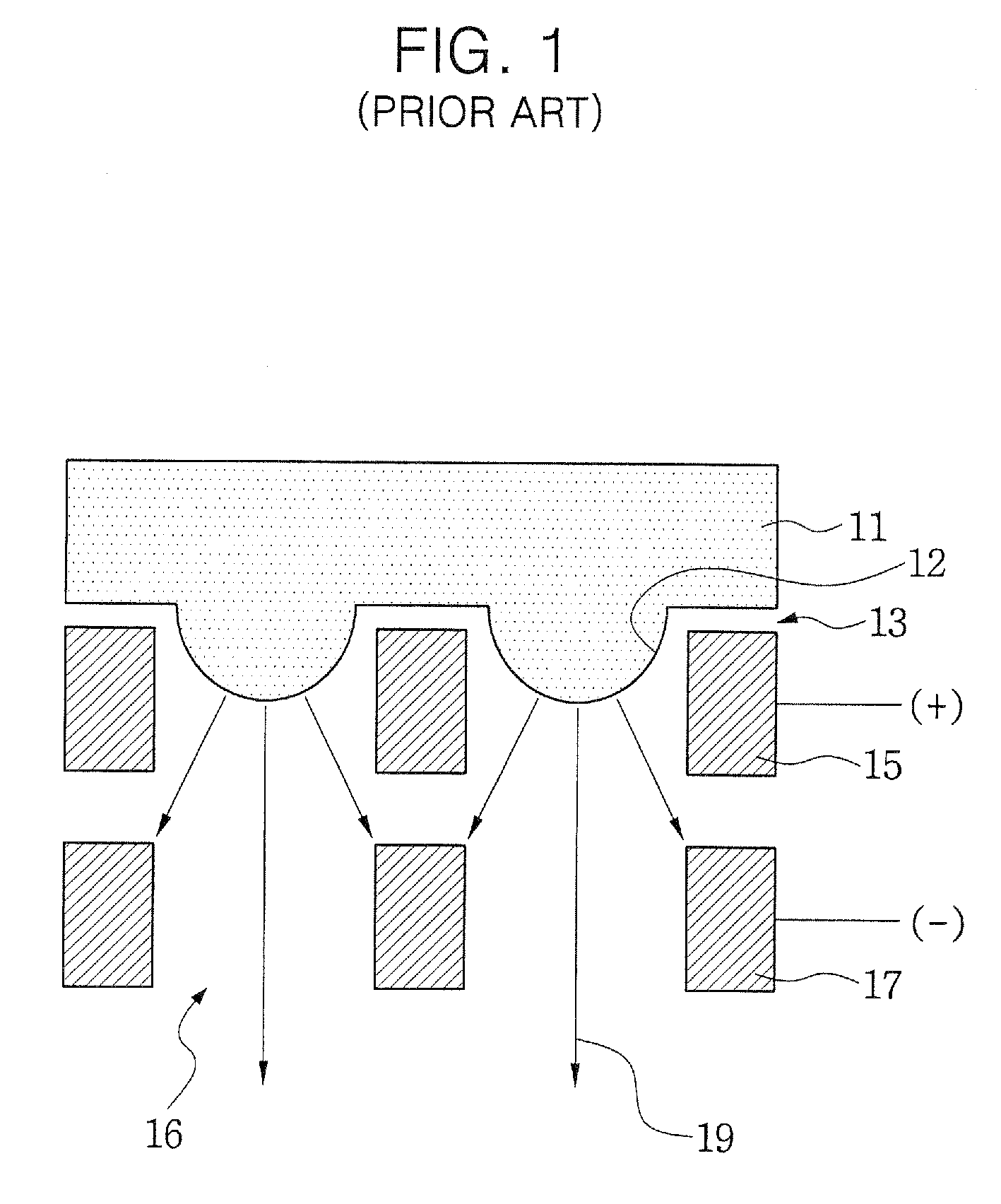
The disadvantage of this deformation of the plasma surface is that the ions in the plasma 11 are extracted in a direction perpendicular to the plasma surface 12.
It therefore becomes impossible to obtain high ion flux of the ion beam 19.
However, an ion beam apparatus capable of increasing ion flux is still required.

Method used


Image

  • Ion beam apparatus having plasma sheath controller
  • Ion beam apparatus having plasma sheath controller
  • Ion beam apparatus having plasma sheath controller

Examples


example

[0085]FIG. 9 illustrates ion current characteristics measured in a first ion extraction grid in order to check variation of ion beams extracted by use of a plasma sheath controller, and FIG. 10 illustrates ion current characteristics measured in a specimen chamber adjacent to a grid assembly in order to check variation of ion beams extracted by use of the plasma sheath controller. Horizontal axes P of FIGS. 9 and 10 denote radio frequency (RF) power applied to an induction coil of a plasma chamber, and the unit is watt (W). Vertical axes Ic of FIGS. 9 and 10 denote measured ion current, and the unit is micro ampere (μA).

[0086]A gas used in the experiment is argon (Ar). A grid assembly including a first ion extraction grid, a second ion extraction grid, and a third ion extraction grid was used. +150V, −100V and 0V were applied to the first ion extraction grid, the second ion extraction grid, and the third ion extraction grid, respectively. The grid assembly had first ion extraction a...


PUM


Abstract

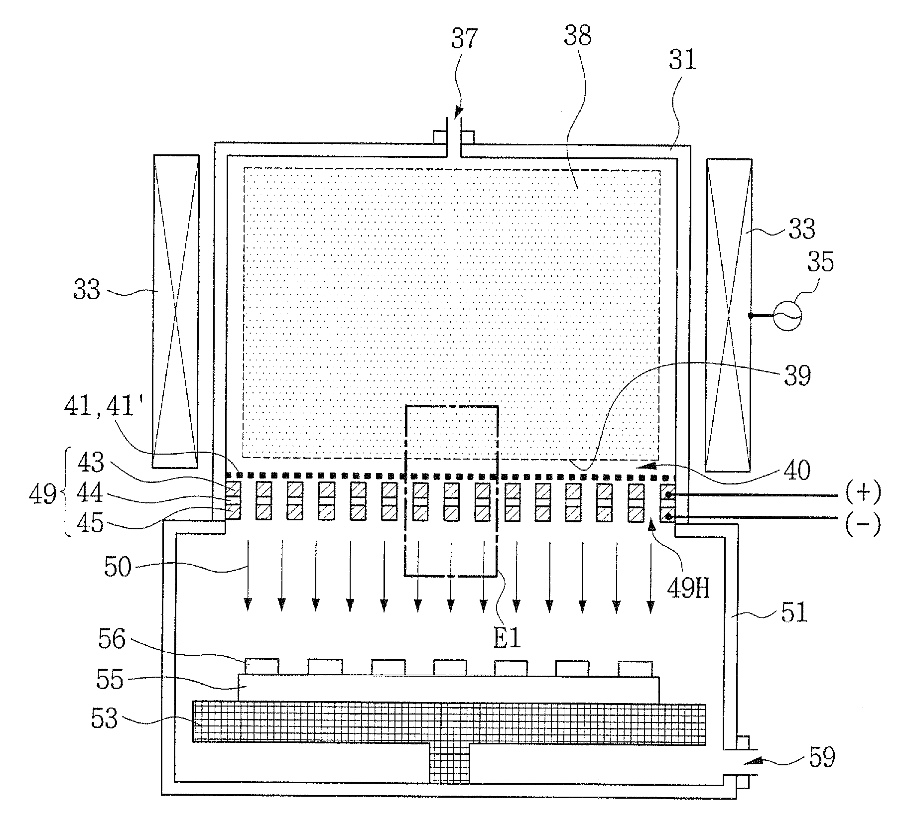
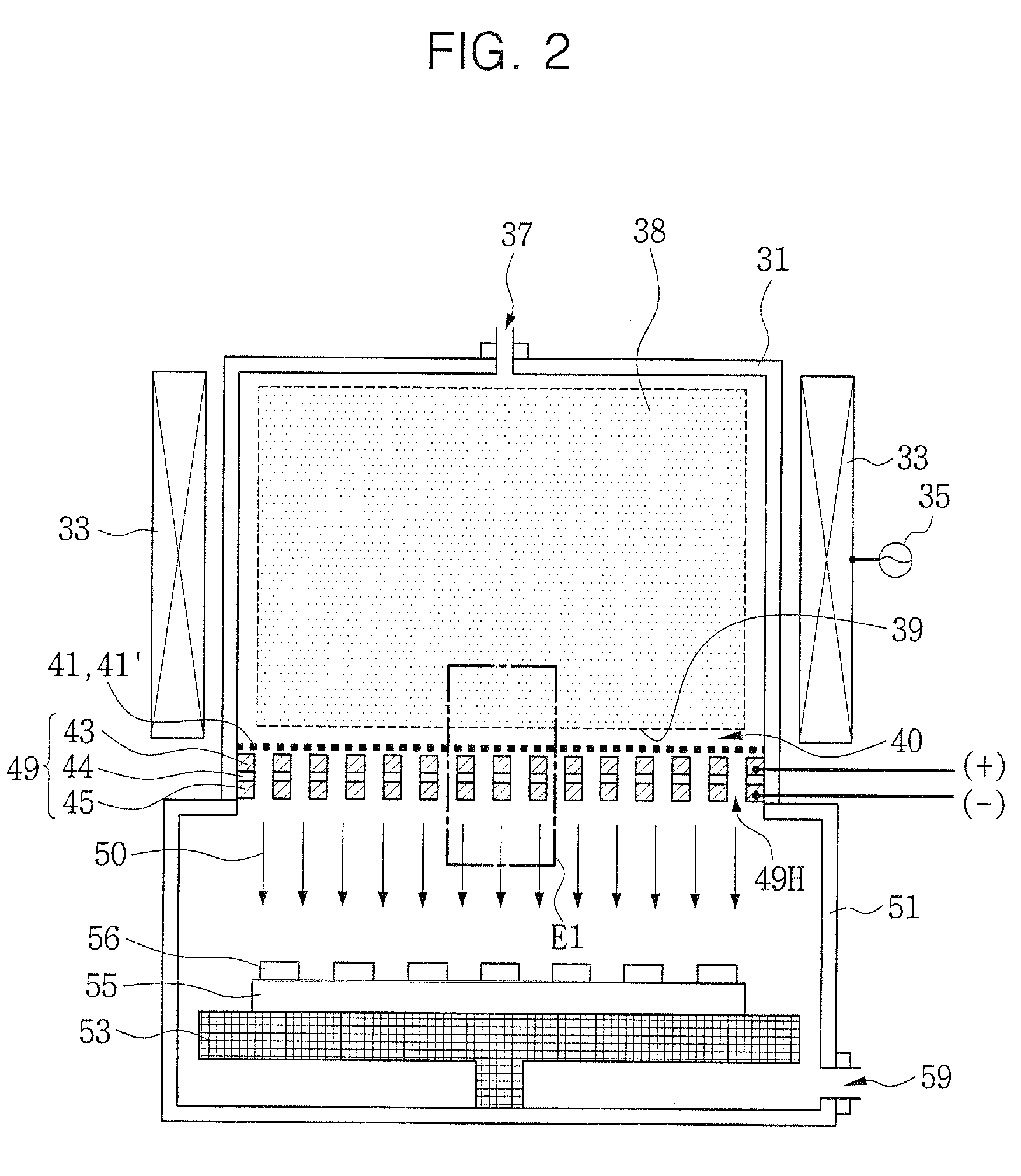
An ion beam apparatus includes a plasma chamber with a grid assembly installed at one end of the plasma chamber and a plasma sheath controller disposed between the plasma chamber and the grid assembly. The grid assembly includes first ion extraction apertures. The plasma sheath controller includes second ion extraction apertures smaller than the first ion extraction apertures. When the plasma sheath controller is used in this configuration, the surface of the plasma takes on a more planar configuration adjacent the controller so that ions, extracted from the plasma in a perpendicular direction to the plasma surface, pass cleanly through the apertures of the grid assembly rather than collide with the sidewalls of the grid assembly apertures. A semiconductor manufacturing apparatus and method for forming an ion beam are also provided.

Description

CROSS-REFERENCE TO RELATED APPLICATION[0001]This application claims the benefit of Korean Patent Application No. 10-2007-0009476, filed Jan. 30, 2007, the disclosure of which is hereby incorporated herein by reference in its entirety.BACKGROUND OF THE INVENTION[0002]1. Field of the Invention[0003]The present invention relates to an apparatus using plasma, and more particularly, to an ion beam apparatus having a plasma sheath controller and a semiconductor surface treatment apparatus employing the same.[0004]2. Description of the Related Art[0005]Semiconductor manufacturing apparatuses using plasma are widely used, for example, a plasma etcher, a plasma enhanced chemical vapor deposition (PECVD) apparatus, a surface treatment apparatus for metal or polymer, a synthesizing apparatus for new materials, an adhesion apparatus for different thin films, and so on. The semiconductor manufacturing apparatuses using plasma may include an ion beam apparatus.[0006]FIG. 1 is a partial cross-sect...

Claims


Application Information

Patent Timeline
IPC IPC(8): H01J37/08
CPCH01J27/024H01J37/08H01J2237/24542H01J2237/061H01J37/3053
Inventor LEE, DO-HAINGHWANG, SUNG-WOOKSHIN, CHUL-HO
Owner SAMSUNG ELECTRONICS CO LTD
Learn More