Phase shifter and bit phase shifter using the same

a phase shifter and bit technology, applied in the direction of delay lines, waveguides, electrical apparatus, etc., can solve the problems of difficult to fabricate inexpensive phase shifters, difficult in conventional phase shifters, and inability to ignore shunt capacitors, etc., to achieve excellent frequency characteristics and inexpensive phase shifters

Inactive Publication Date: 2008-07-31
RENESAS ELECTRONICS CORP
View PDF5 Cites 26 Cited by
  • Summary
  • Abstract
  • Description
  • Claims
  • Application Information

AI Technical Summary

Benefits of technology

[0023]According to the present invention, the phase shifter with excellent frequency characteristics in high frequencies can be provided, and an inexpensive phase shifter can also be provided. Moreover, various kinds of phase shifters can be fabricated.

Problems solved by technology

However, it is difficult in a conventional phase shifter to satisfy requirement for the inexpensive phase shifter and requirement for the phase shifter with excellent high-frequency performance.
Therefore, it is extremely difficult to fabricate an inexpensive phase shifter.
However, following problems arise depending on a specific frequency band to be used and a phase shift amount.
However, it is not possible in the shunt capacitor to ignore effect of a parasitic inductance caused by extending a wiring pattern in a high frequency band.
Therefore, it is difficult to use a capacity of a small capacitance.
In order to realize a small capacitance of the shunt capacitor, problems arise such as increase of factors to process variations and increase of a phase shift error.
Meanwhile, in case of the switched line type of phase shifter, a large difference in the line length is required for a large phase shift amount.
Accordingly, there are drawbacks such as arrangement of a long transmission line and an increased chip size.
As a result, the cost increases.
Therefore, either frequency characteristics or costs are sacrificed in the conventional phase shifters.

Method used


Image

  • Phase shifter and bit phase shifter using the same
  • Phase shifter and bit phase shifter using the same
  • Phase shifter and bit phase shifter using the same

Examples


Embodiment Construction

[0030]Hereinafter, a phase shifter according to embodiments of the present invention will be described in detail with reference to the attached drawings.

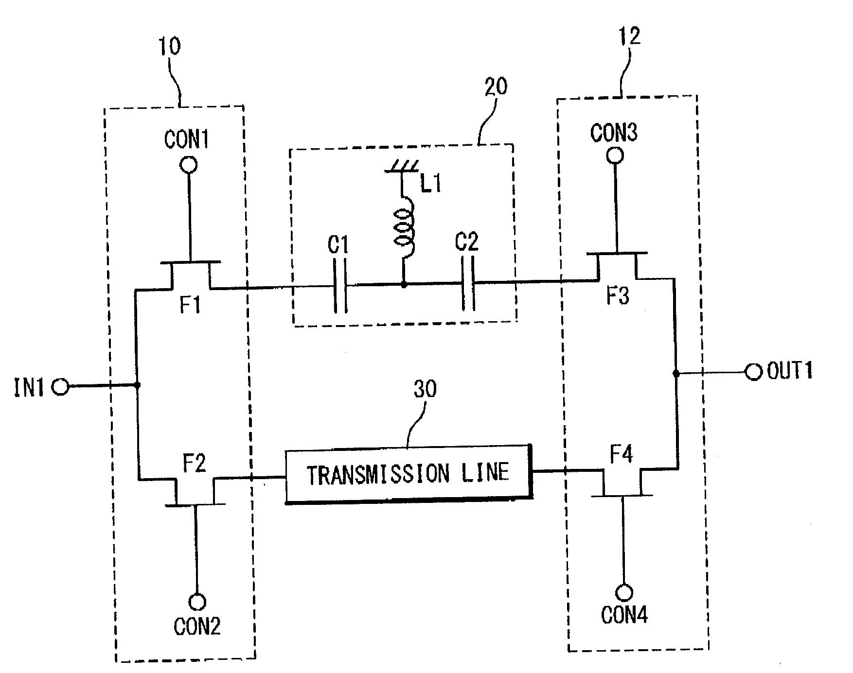
[0031]FIG. 3 shows a basic configuration of the phase shifter according to a first embodiment of the present invention. In the first embodiment, switches 10 and 12 for switching signal paths are provided, and a high pass filter (HPF) 20 is arranged in one of the signal paths and a microstrip transmission line 30 is arranged in the other signal path.

[0032]An operation of the phase shifter according to the present embodiment will be described with reference to FIG. 3. In FIG. 3, when ON voltages are applied to a control terminal CON1 and a control terminal CON3, and OFF voltages are applied to a control terminal CON2 and a control terminal CON4, an FET F1 and an FET F3 are turned on, and an FET F2 and an FET F4 are turned off. At this time, a microwave signal is inputted from an input terminal IN1 and is outputted from an output termi...


PUM


Abstract

A phase shifter includes a first signal path in which a first unit is disposed to advance a phase of a signal; a second signal path in which a second unit with no shunt capacitor is disposed to change the phase of the signal such that the changed phase is delayed than the advanced phase by the first unit; and a switch section configured to switch between the first signal path and said second signal path. The first unit comprises a filter, and the second unit is a transmission line.

Description

BACKGROUND OF THE INVENTION[0001]1. Field of the Invention[0002]The present invention relates to a phase shifter and a bit phase shifter using the same. This Patent Application claims priority based on Japanese Patent application No. 2007-021725. The disclosure of the Japanese Patent application is incorporated herein by reference.[0003]2. Description of the Related Art[0004]The phased array technique has been used for special purposes such as a radar and is used in commercial products in recent years. Application of the technique is further considered to receive satellite broadcasting. A phase shifter is indispensable to use the phased array technique. In accordance with extension of application fields of the phased array technique, a demand is increasing for an inexpensive phase shifter suitable for commercial products and a satisfactory phase shifter having excellent high-frequency performance and suitable for receiving satellite broadcasting. However, it is difficult in a conven...

Claims


Application Information

Patent Timeline
Patent Type & Authority Applications(United States)
IPC IPC(8): H01P1/18
CPCH03H7/20H01P1/18
Inventor MIYA, TATSUYA
Owner RENESAS ELECTRONICS CORP
Why Eureka
Try Eureka