Enhanced seeded pulsed fiber laser source

a laser source and seeded fiber technology, applied in the field of laser light sources, can solve the problems of limiting the maximum achievable output power of the source and its stability, and the extinction ratio of the modulator must be high

Inactive Publication Date: 2008-07-31
INSTITUT NATIONAL D'OPTIQUE
View PDF5 Cites 51 Cited by
  • Summary
  • Abstract
  • Description
  • Claims
  • Application Information

AI Technical Summary

Problems solved by technology

Another drawback of the self-seeded source of LAROSE et al. is that the modulator extinction ratio must be high in order to prevent spurious lasing of the source due to the parasitic back reflections coming from the output isolator or from other components such as the pump couplers.
This ultimately limits the maximum achievable output power of the source and its stability, depending on both the modulator extinction ratio and the back reflection level of the other optical components.
However, when laser diode (preferably single transverse mode) seed sources are available with the required line-width, it is sometimes advantageous to use a seeded geometry for generating a pulsed laser output.
This is the case when the modulation device for generating the pulsed laser output has a low optical power damage threshold.

Method used


Image

  • Enhanced seeded pulsed fiber laser source
  • Enhanced seeded pulsed fiber laser source
  • Enhanced seeded pulsed fiber laser source

Examples


Embodiment Construction

[0025]In the following description, the term “light” is used to refer to all electromagnetic radiation, including but not limited to visible light. Furthermore, the term “optical” is used to qualify all electromagnetic radiation, that is to say light in the visible spectrum and light in other wavelength ranges.

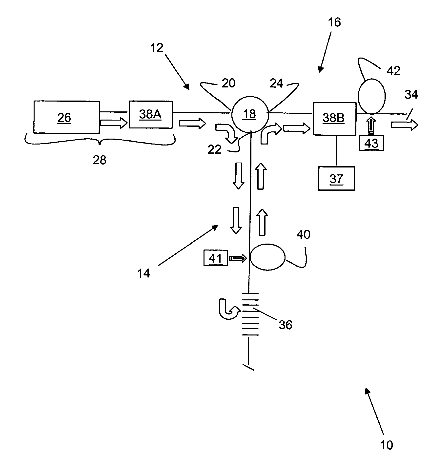
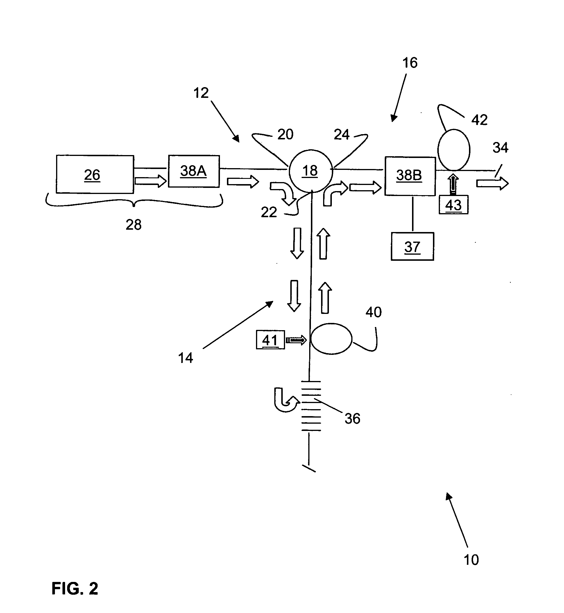
[0026]A pulsed laser light source (10) for producing amplified light pulses is shown in FIGS. 2 and 3 according to two preferred embodiments of the invention. As will be apparent from the description below for one skilled in the art, the pulsed laser light source of the present invention provides great versatility in shaping the temporal and spectral profile of the light beam while using readily available and relatively inexpensive components. The temporal profile of the light beam is defined as its intensity as a function of time and defines the width, repetition rate and amplitude shape of the light pulses. The spectral profile of the light beam is defined as its intensity a...


PUM


Abstract

A pulsed laser light source for producing amplified light pulses is provided. It includes a three-port optical circulator connected to a first, second, and third waveguide branch, a seed module for generating a pulsed light and propagating the light along the first waveguide branch to the first port of the optical circulator and out the second port to the second waveguide branch, a reflector in the second waveguide branch for reflecting the light back through the second port of the optical circulator for circulation out the third port to the third waveguide branch, and a light output provided in the third waveguide branch for outputting the amplified light pulses. An amplifier is disposed in the second waveguide branch between the optical circulator and the reflector for amplifying the light and an optical modulator operable for modulating the pulsed light is disposed in the third waveguide branch.

Description

FIELD OF THE INVENTION[0001]The present invention relates generally to the field of laser light sources and more particularly concerns an enhanced seeded pulsed fiber laser source with unfolded cavity design which provides efficient energy extraction and optical pulses with pulse shape flexibility.BACKGROUND OF THE INVENTION[0002]Pulsed laser light sources are used in a variety of fields such as material processing, dentistry, range finding, remote sensing, LIDAR (Light Detection and Ranging) or communication-related applications. Different applications require pulsed lasers with different output power; however it is usually desirable to produce a high peak power from a pulsed laser. In general, three techniques are used for this purpose: Q-switching, mode-locking, and gated cascade amplification.[0003]The Q-switching method consists of switching from a high-loss (low quality i.e. low Q) to a low-loss (high quality i.e. high Q) condition in a laser cavity. A Q-switched laser system ...

Claims


Application Information

Patent Timeline
Patent Type & Authority Applications(United States)
IPC IPC(8): H01S3/10
CPCH01S3/005H01S3/0085H01S2301/02H01S3/10015H01S3/2333H01S3/06758
Inventor DELADURANTAYE, PASCALLAROSE, ROBERTTAILLON, YVESBRUNET, FRANCOIS
Owner INSTITUT NATIONAL D'OPTIQUE
Why Eureka
Try Eureka