Pre-amplifier for detection lasers within laser ultrasonic inspection systems

a laser inspection and ultrasonic technology, applied in the direction of instruments, specific gravity measurement, digital computer details, etc., can solve the problems of affecting labor-intensive, expensive, and strict quality control procedures, and achieve the effect of reducing the manufacturing cost of composite structures, and reducing the cost of manufacturing

Active Publication Date: 2008-07-31
LOCKHEED MARTIN CORP
View PDF6 Cites 13 Cited by
  • Summary
  • Abstract
  • Description
  • Claims
  • Application Information

AI Technical Summary

Problems solved by technology

While composite materials offer significant improvements in performance, they require strict quality control procedures in both the manufacturing processes and after the materials are in service in finished products.
Conventional NDE methods are slow, labor-intensive, and costly.
As a result, testing procedures adversely increase the manufacturing costs associated with composite structures.
However, the equipment used for laser ultrasound is custom-designed and is presently a limiting factors regarding inspection speed.
Inspection speed is currently limited by the pulse rate of the lasers.
Therefore these lasers are slow and expensive to operate.
Diode-pumped slabs are much faster (400 Hz is current limit and 1 Khz may be possible) but they use very expensive custom-manufactured diode arrays to pulse-pump the slabs and create a great amount of heat which can induce thermal distortion.
Although diode array lifetimes are getting Wetter, some have lasted 102 shots, they have historically been a concern due to both high-cost, reliability and thermal distortion.
High-power pulsed-diode pumping of a crystal slab will introduce thermal distortions into the slab that ultimately limits the waveform quality of the laser beam.
Wavefront distortion can limit the useful power of a laser and prevent efficient fiber optic delivery of the beam to the target.
Heat removal is a significant design issue for both the diode arrays and the slab.

Method used


Image

  • Pre-amplifier for detection lasers within laser ultrasonic inspection systems
  • Pre-amplifier for detection lasers within laser ultrasonic inspection systems
  • Pre-amplifier for detection lasers within laser ultrasonic inspection systems

Examples


Embodiment Construction

[0026]Preferred embodiments of the present invention are illustrated in the FIGs., like numerals being used to refer to like and corresponding parts of the various drawings.

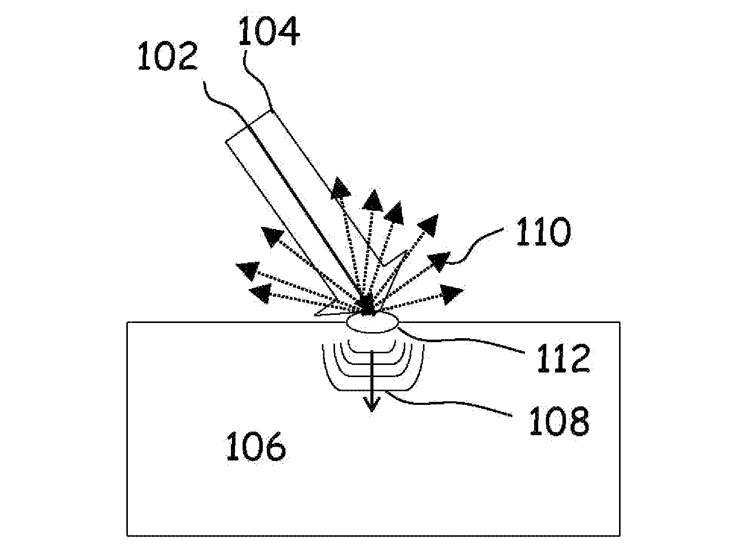
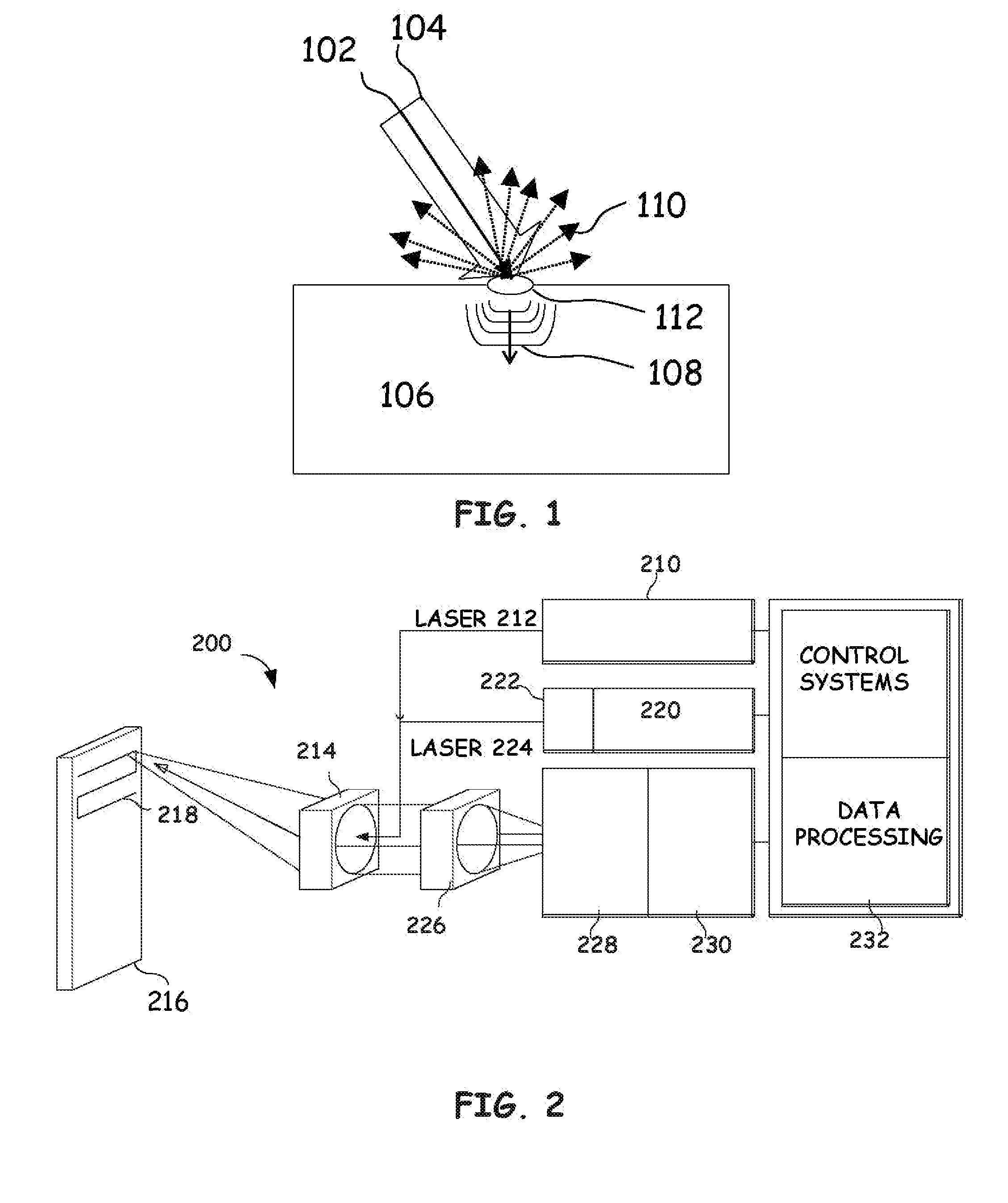
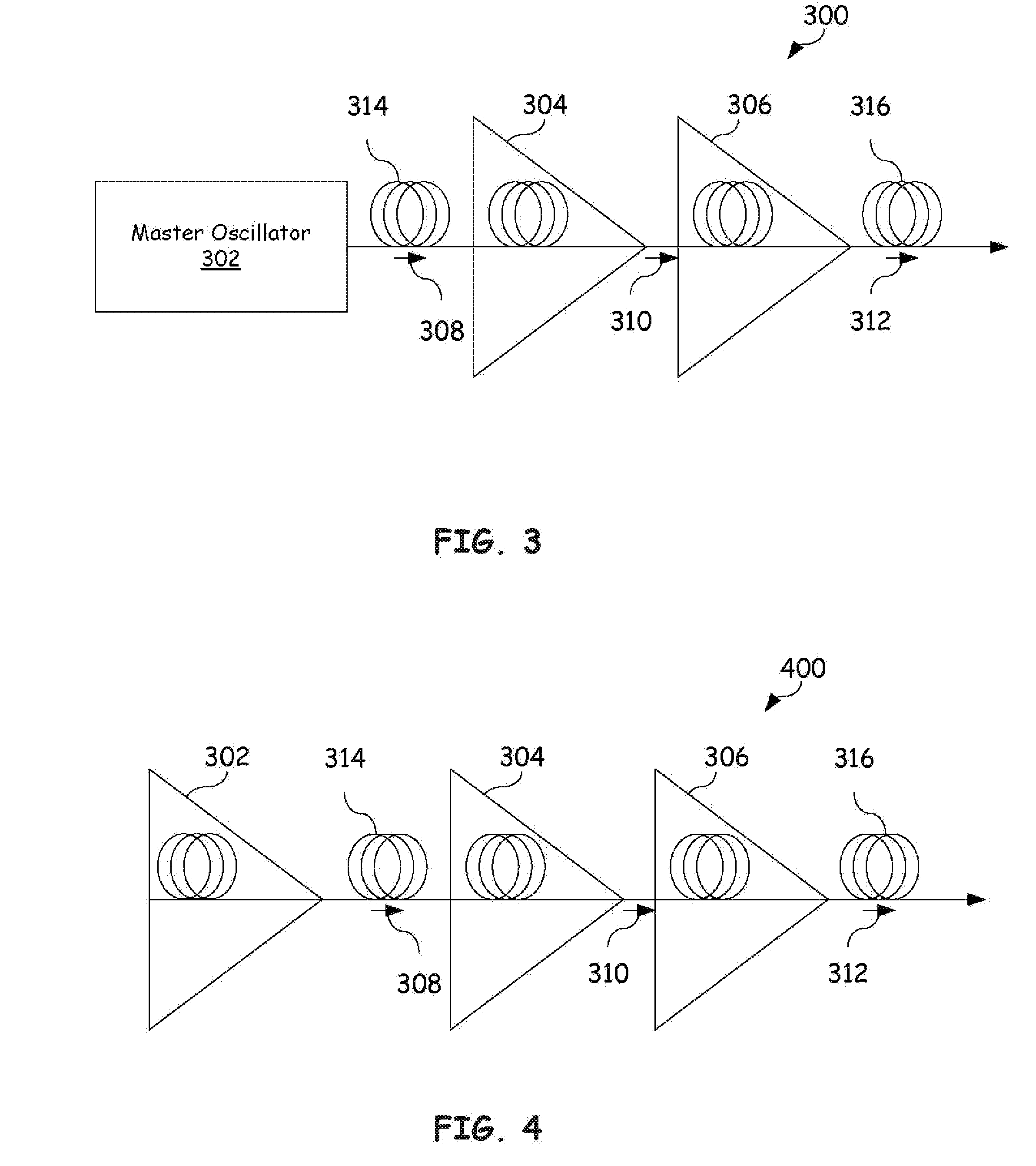
[0027]Embodiments of the present invention provide a detection laser for use within a laser ultrasound system. A pulse detection laser is provided by embodiments of the present invention. The pulse detection laser includes a single frequency oscillator, a continuous pre-amplifier, and a pulsed amplifier. The single frequency oscillator generates a seed laser beam and is optically coupled to the continuous preamplifier. The continuous pre-amplifier amplifies the seed laser to produce an intermediate power laser beam. A pulsed amplifier optically coupled to the continuous pre-amplifier receives the intermediate power laser beam and amplifies the intermediate power laser beam to produce a pulse detection laser beam. One task of this pulse detection laser is to illuminate ultrasonic displacements. Light from the lase...


PUM


Abstract

A pulse detection laser is provided. The pulse detection laser includes a single frequency oscillator, a continuous pre-amplifier, and a pulsed amplifier. The single frequency oscillator generates a seed laser beam and is optically coupled to the continuous preamplifier. The continuous pre-amplifier amplifies the seed laser to produce an intermediate power laser beam. A pulsed amplifier optically coupled to the continuous pre-amplifier receives the intermediate power laser beam and amplifies the intermediate power laser beam to produce a pulse detection laser beam. One task of this pulse detection laser is to illuminate ultrasonic displacements. Light from the laser is scattered, collected, and analyzed with an interferometer to demodulate the ultrasonic displacements caused by the return echoes of the ultrasound at the surface of the part.

Description

RELATED APPLICATIONS[0001]This application claims priority to and incorporates by reference in its entirety for all purposes U.S. Provisional Application No. 60 / 871,680 filed on 22 Dec. 2006 entitled “ARTICULATED ROBOT FOR LASER ULTRASONIC INSPECTION” to Thomas E. Drake.[0002]This application incorporates by reference in its entirety for all purposes U.S. Provisional Application No. 60 / 091,240 filed on 30 Jun. 1998.[0003]This application incorporates by reference in its entirety for all purposes U.S. Provisional Application No. 60 / 091,229 filed on 30 Jun. 1998 entitled “METHOD AND APPARATUS FOR DETECTING ULTRASONIC SURFACE DISPLACEMENTS USING POST-COLLECTION OPTICAL AMPLIFICATION” to Thomas E. Drake.[0004]This application incorporates by reference in its entirety for all purposes U.S. patent application Ser. No. 10 / 753,208 filed on 7 Jan. 2004 and entitled “REMOTE LASER BEAM DELIVERY SYSTEM AND METHOD FOR USE WITH A ROBOTIC POSITIONING SYSTEM FOR ULTRASONIC TESTING PURPOSES” to Thom...

Claims


Application Information

Patent Timeline
Patent Type & Authority Applications(United States)
IPC IPC(8): G01B11/16H01S3/13
CPCG01H9/008G01N21/1702G01N2291/0231G01N2021/1706G01N29/2418G01N29/24G01N21/17G01H9/00
Inventor DUBOIS, MARCDRAKE, THOMAS E.YAWN, KENNETH R.
Owner LOCKHEED MARTIN CORP
Why Eureka
Try Eureka