Drive transmission mechanism between two or more rotary shafts and oil-free fluid machine equipped with the mechanism

a transmission mechanism and rotary shaft technology, applied in the direction of positive displacement liquid engine, piston pump, liquid fuel engine, etc., can solve the problems of synchronization gear synchronization gears that require no lubricant, and load torque exerted on synchronization gears, so as to prolong the operation life of synchronization gears and facilitate replacement of synchronization gears when worn. , the effect of increasing the torque transmission capacity

Inactive Publication Date: 2008-07-31
ANEST IWATA CORP
View PDF7 Cites 122 Cited by
  • Summary
  • Abstract
  • Description
  • Claims
  • Application Information

AI Technical Summary

Benefits of technology

[0011]Therefore, the object of the invention is to provide a drive transmission mechanism with which torque transmission can be performed between two or more rotary shafts in synchronized counter-rotation with one another without need for lubrication oil thereby eliminating contamination induced by lubrication oil and without reduction of operation life, and an oil-free fluid machine equipped with the drive transmission mechanism.
[0014]By composing as mentioned above the drive transmission mechanism such that magnetic drive disks each consisting of a magnet carrier disk made of nonmagnetic material and a plurality of magnets arranged on one side face of the magnet carrier disk circumferentially at equal spacing are attached to rotary shafts respectively at one side end thereof and synchronization gears are attached to the rotary shafts at the other end side thereof respectively, a part of torque transmission is done via the magnetic drive disks and the remaining torque transmission is done via the synchronization gears. Therefore, load torque exerting on the synchronization gears is reduced, and plastic gear or gears can be adopted for the synchronization gears, resulting in requiring no lubricant to lubricate the synchronization gears and prolonged operation life of the synchronization gears. Therefore, by adopting the drive transmission mechanism in an oil-free fluid machine, contamination with lubricating oil can be eliminated, and particularly a dry mechanical vacuum pump of high efficiency which can produce oil-free vacuum can be provided.
[0016]By providing the synchronization gears in a side opposite to a side where a drive device is connected to one of the rotary shafts, replacement of synchronization gears when they have worn is facilitated.
[0017]By attaching the plurality of magnets on one side surface of the magnetic drive disks respectively, and fixing the magnetic drive disks to the rotary shafts respectively such that the magnets of respective driving disks face each other with a small gap maintained between the magnets as the driving disks rotate, torque transmission capacity is increased, since the gap between the magnets facing one another can be reduced to a minimum.
[0018]As has been described in the foregoing, according to the drive transmission mechanism of the invention, as torque transmission between the rotary shafts is carried out in two ways, via the magnetic drive disks and via the synchronization gears, load torque exerting on the synchronization gears is reduced, and plastic gear or gears can be adopted for the synchronization gears, resulting in requiring no lubricant to lubricate the synchronization gears and prolonged operation life of the synchronization gears. Therefore, by adopting the drive transmission mechanism in an oil-free fluid machine, contamination with lubricating oil can be eliminated, and particularly a dry mechanical vacuum pump of high efficiency which can produce oil-free vacuum can be provided.

Problems solved by technology

Therefore, load torque exerting on the synchronization gears is reduced, and plastic gear or gears can be adopted for the synchronization gears, resulting in requiring no lubricant to lubricate the synchronization gears and prolonged operation life of the synchronization gears.

Method used


Image

  • Drive transmission mechanism between two or more rotary shafts and oil-free fluid machine equipped with the mechanism
  • Drive transmission mechanism between two or more rotary shafts and oil-free fluid machine equipped with the mechanism
  • Drive transmission mechanism between two or more rotary shafts and oil-free fluid machine equipped with the mechanism

Examples


Embodiment Construction

[0023]A preferred embodiment of the present invention will now be detailed with reference to the accompanying drawings. It is intended, however, that unless particularly specified, dimensions, materials, relative positions and so forth of the constituent parts in the embodiments shall be interpreted as illustrative only not as limitative of the scope of the present invention.

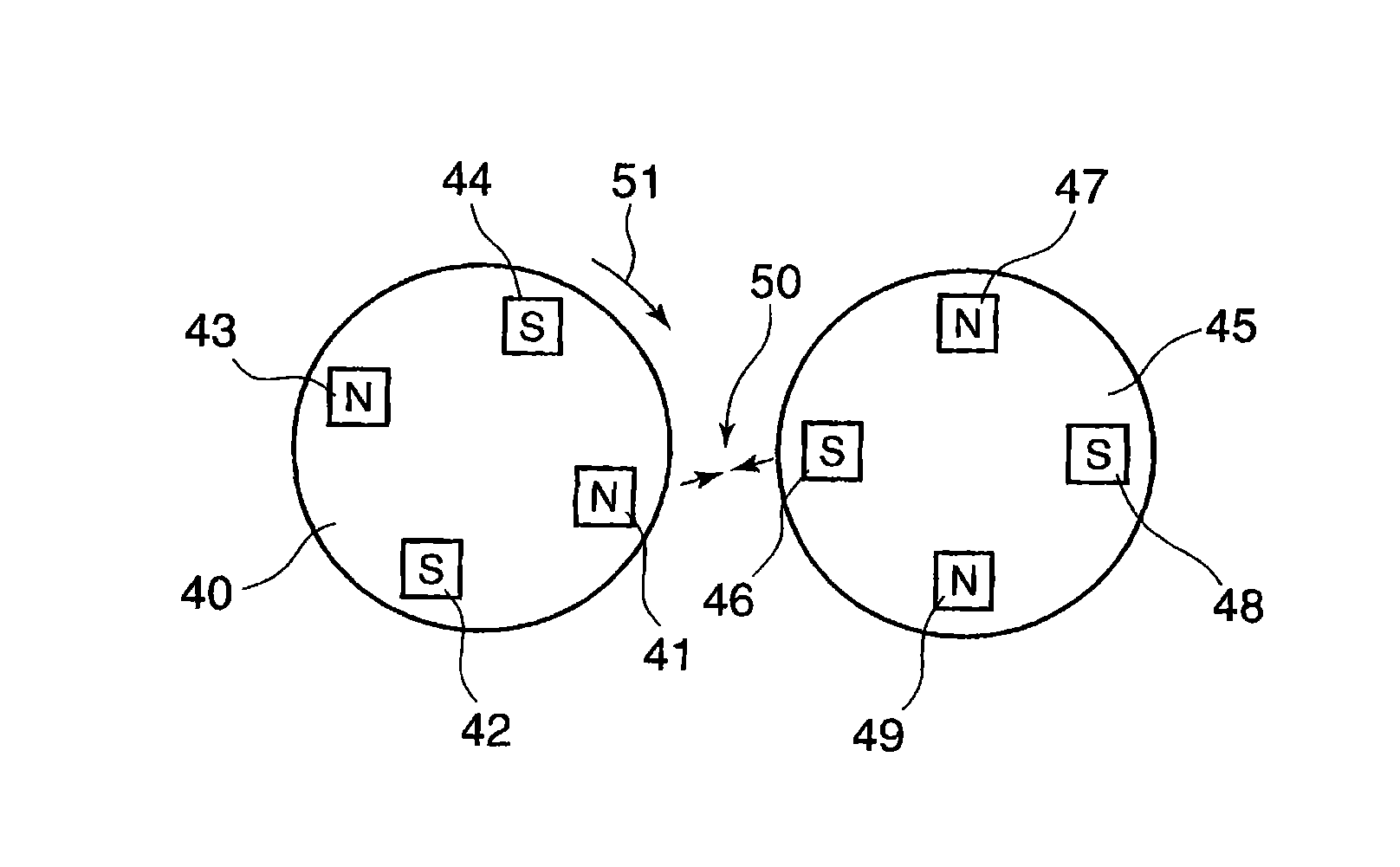
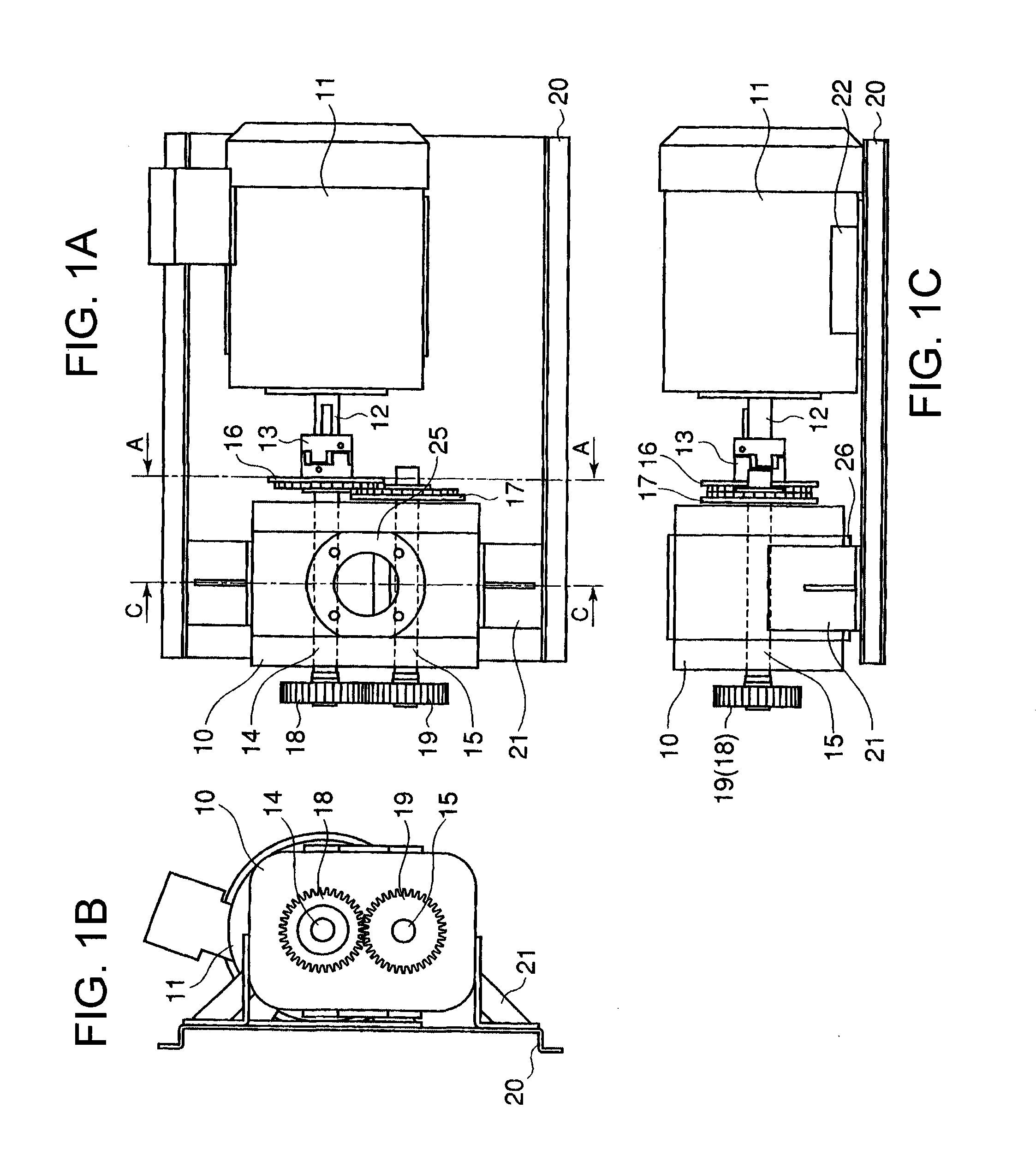
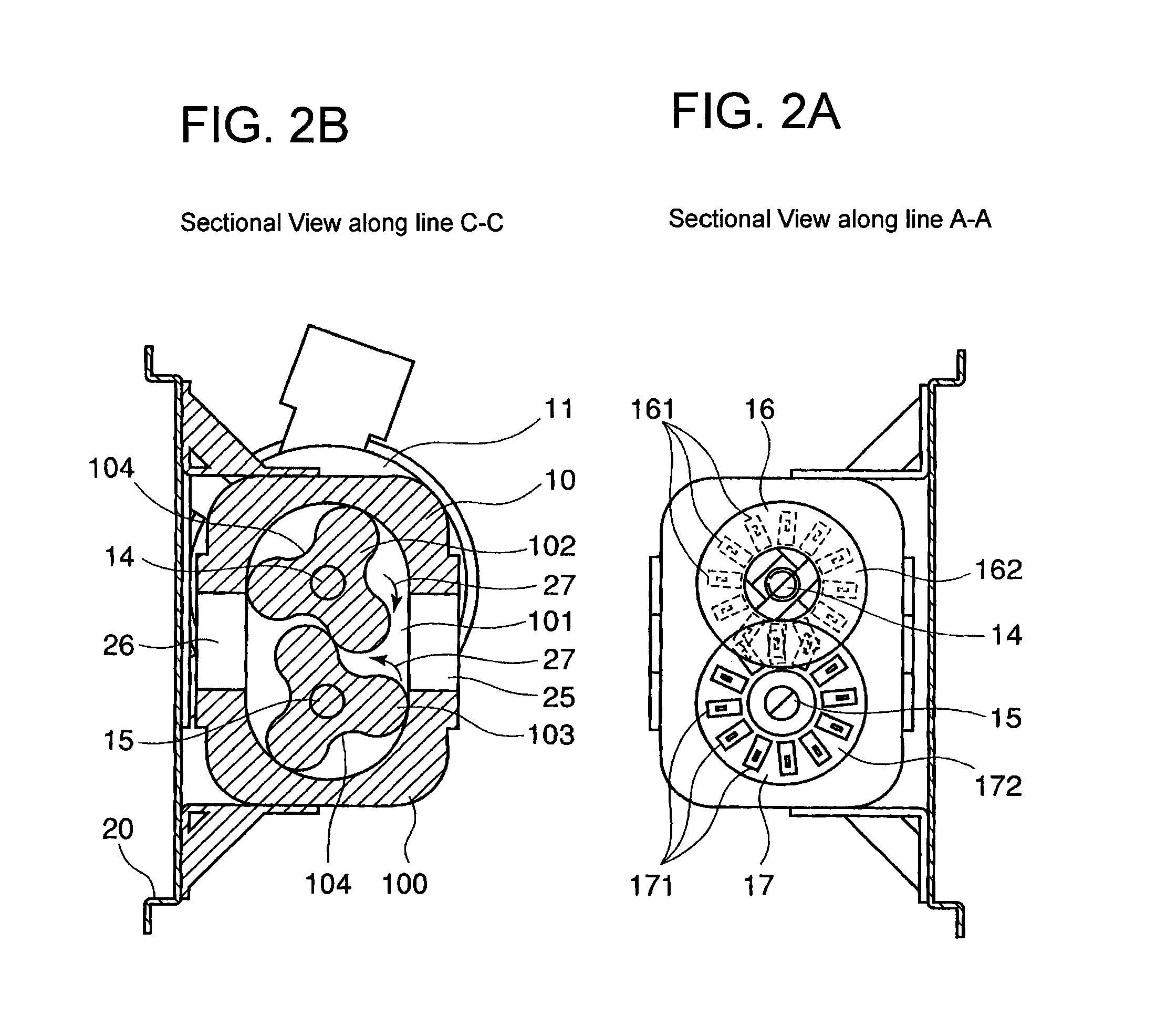
[0024]FIG. 1A is a plan view of the oil-free fluid machine composed as a dry mechanical vacuum pump of roots type equipped with the drive transmission mechanism according to the present invention, FIG. 1B is a front view thereof, and FIG. 1C is a side view thereof. FIG. 2A is a sectional view along line A-A in FIG. 1A, and FIG. 2B is a cross sectional view along Line C-C in FIG. 1A.

[0025]Although the invention will be explained taking up as an example a dry mechanical vacuum roots pump of two rotors equipped with the drive transmission mechanism, the drive transmission mechanism of the invention can be applied t...


PUM


Abstract

A drive transmission mechanism for transmitting torque between two or more rotary shafts in synchronization with one another without need for lubrication thereby eliminating occurrence of oil contamination, and an oil-free fluid machine equipped with the mechanism, are provided. A magnetic drive disk 16 and a synchronization gear 18 are attached to a rotary shaft 14 connected to a drive motor 11, a magnetic drive disk 17 and a synchronization gear 19 is attached to a rotary shaft 15, torque transmission from the rotary shaft 14 to the rotary shaft 15 is carried out in two ways, via the magnetic drive disks 16, 17 and via the synchronization gears 18, 19, and at least one of the synchronization gears is made of plastic material. With the construction, torque transmit load between the rotary shafts via the synchronization gears is decreased, and a plastic gear or gears can be adopted for synchronization gears without reducing life of the gears without need for lubrication oil.

Description

BACKGROUND OF THE INVENTION[0001]1. Field of the Invention[0002]The present invention relates to a mechanism for transmitting driving force between two or more rotary shafts, specifically to a drive transmission mechanism with which rotors of a dry-sealed mechanical vacuum pump such as Roots type, screw type, and claw type vacuum pump having two or more rotors can be rotated in synchronism with one another without a need for lubrication oil for lubricating the mechanism thereby eliminating occurrence of oil contamination and to an oil-free fluid machine equipped with the mechanism.[0003]2. Description of the Related Art[0004]Fluid machines having two or more counter-rotating meshed lobed rotors accommodated in a rotor casing to expel air trapped in a space between the wall of the casing and the rotor surface by rotating the rotors in synchronization with one another are widely used as vacuum pumps such as roots vacuum pumps, claw vacuum pumps, and screw vacuum pumps.[0005]In these d...

Claims


Application Information

Patent Timeline
Patent Type & Authority Applications(United States)
IPC IPC(8): F01C1/18H02K49/00
CPCF04C25/02Y10T464/30F04C29/0064F04C29/005
Inventor TANIGAWA, SHIRONAKAYAMA, TAKAMITSUTAKADA, YUKI
Owner ANEST IWATA CORP
Why Eureka
Try Eureka