Downhole Multi-Phase Flow Imager

a multi-phase flow and imager technology, applied in the field of downhole evaluation, can solve the problems of complex measurement of dielectric permittivity and conductivity, sensor stability and accuracy, and inability to effectively operate dielectric permittivity sensors in a conductive medium

Inactive Publication Date: 2008-07-31
BAKER HUGHES INC
View PDF25 Cites 19 Cited by
  • Summary
  • Abstract
  • Description
  • Claims
  • Application Information

AI Technical Summary

Benefits of technology

[0022]One embodiment of the disclosure is an apparatus for evaluating multiphase fluid flow in a borehole. The apparatus includes a housing insertable in the borehole at a desired position and having a plurality of sensors. Each of the plurality of sensors includes a transmitter electrode in contact with the fluid and having a low output admittance, a detector electrode in contact with the fluid and having a low input impedance, and a generator engaged with the housing and connected with the transmitter electrode configured to charge the transmitter electrode. The apparatus also includes circuitry which provides a difference between a signal from a detector electrode of one of the plurality of sensors and a combined signal from the detector electrode of a plurality of sensors. This circuitry may be analog circuitry. The apparatus may further include a processor configured to determine from the difference signal an evaluation of the multiphase fluid. The processor may be configured to make the determination based at least in part on a geometric factor of the transmitter electrode with the detector electrode. The processor may be for the configured to produce an image of the multiphase fluid. The processor may be for the configured to estimate a velocity of flow of the multiphase fluid. The detector electrode may be shielded from the transmitter electrode.
[0023]Another embodiment of the disclosure is a method of evaluating a multiphase fluid in a borehole. The method includes conveying a housing in the borehole to a desired downhole position, making measurements at a plurality of sensors on the housing a transmitter electrode having a low output admittance on each of the plurality of sensors in contact with the fluid, and a detector electrode on each of the plurality of sensors having a l

Problems solved by technology

However, dielectric permittivity sensors cannot effectively operate in a conductive medium where the conductivity of the formation fluid exceeds 0.0001 S/m.
Although downhole sensors have been constructed to evaluate the dielectric properties of formation fluids, such sensors do not provide stable and accurate results when the fluids

Method used


Image

  • Downhole Multi-Phase Flow Imager
  • Downhole Multi-Phase Flow Imager
  • Downhole Multi-Phase Flow Imager

Examples


Embodiment Construction

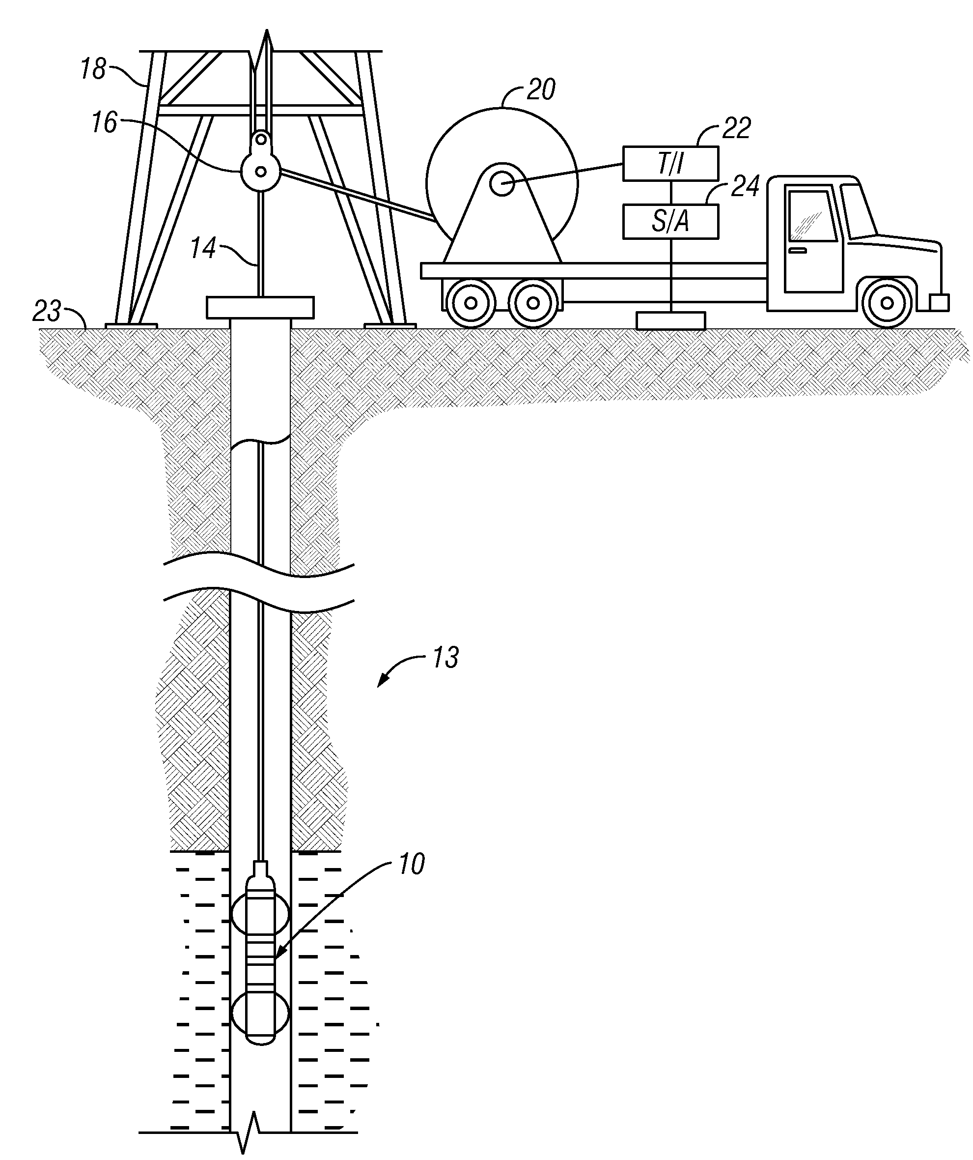
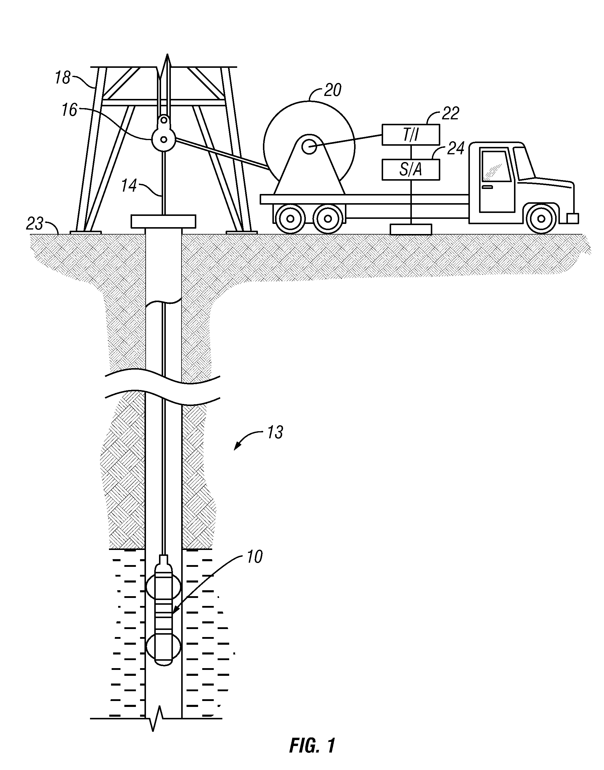
[0032]FIG. 1 shows flow-rate sensor tool 10 suspended in a borehole 12, that penetrates earth formations such as 13, from a suitable cable 14 that passes over a sheave 16 mounted on drilling rig 18. This is for illustrative purposes only, and the flow-rate sensor tool may be permanently deployed in a borehole. The borehole may be vertical, deviated, or horizontal. For deployment in horizontal boreholes, devices such as coiled tubing or tractors may be used. By industry standard, the cable 14 includes a stress member and seven conductors for transmitting commands to the tool and for receiving data back from the tool as well as power for the tool. The tool 10 is raised and lowered by draw works 20. Electronic module 22, on the surface 23, transmits the required operating commands downhole and in return, receives data back which may be recorded on an archival storage medium of any desired type for concurrent or later processing. The data may be transmitted in analog or digital form. Da...


PUM


Abstract

Dynamic gain setting is provided for a multiphase flow measuring device that measures in-phase and quadrature signals. The average current at a plurality of measure electrodes is determined and subtracted from the individual measure currents to give a measurement with improved dynamic range.

Description

CROSS-REFERENCES TO RELATED APPLICATIONS[0001]This application is a continuation in part of U.S. patent application Ser. No. 11 / 201,251 filed on Aug. 10, 2005.BACKGROUND OF THE INVENTION[0002]1. Field of the Invention[0003]The present invention relates to the downhole evaluation of formation fluids produced into a wellbore. More particularly, the present invention relates to a system that simultaneously combines conductivity and dielectric permittivity sensors in a single downhole module for real-time multiphase flow evaluation.[0004]2. Background of the Art[0005]Fluids are produced from a borehole drilled into the formation rock. The fluids are tested to evaluate the presence of hydrocarbons, the flow-rate, and the presence of multiphase fluids created by the combination of water and hydrocarbons. The resulting data provides information regarding the concentration of hydrocarbons in the formation. The data also provides information regarding the composition and location of hydrocar...

Claims


Application Information

Patent Timeline
IPC IPC(8): E21B47/10
CPCG01V3/24
Inventor FORGANG, STANISLAV W.
Owner BAKER HUGHES INC
Why Eureka
Try Eureka