Method for regulating a hydrostatic drive system

a technology of hydrostatic drive and control system, which is applied in the direction of clutches, fluid couplings, gearing elements, etc., can solve the problem that the control of the pump merely as a function of the throttle pedal position is generally not sufficient for comfortable vehicle operation, and achieves the effect of greater intervention into the rest of the driving behaviour

Inactive Publication Date: 2008-08-07
SAUER DANFOSS NORDBERG
View PDF5 Cites 13 Cited by
  • Summary
  • Abstract
  • Description
  • Claims
  • Application Information

AI Technical Summary

Benefits of technology

[0010]The adjustment of the hydraulic motor preferably takes place by means of an electrically proportional adjusting unit. In another embodiment of the invention, the method can also be applied in the case of a hydraulic follow-up adjustment. This has the advantage that the regulating procedure can be installed in construction, forestry and agricultural machines with different travel controllers without greater interventions into the rest of the driving behaviour.

Problems solved by technology

The control of the pump merely as a function of the throttle pedal position is generally not sufficient for comfortable operation of the vehicle.
In particular the power consumption capacity of the pumps is generally a multiple of the nominal power of the internal combustion engine, which necessitates a corresponding power limitation of the hydrostatic drive, which power limitation prevents stalling of the internal combustion engine in load operation and prevents over-revving of the internal combustion engine in overrun operation.

Method used


Image

  • Method for regulating a hydrostatic drive system
  • Method for regulating a hydrostatic drive system
  • Method for regulating a hydrostatic drive system

Examples


Embodiment Construction

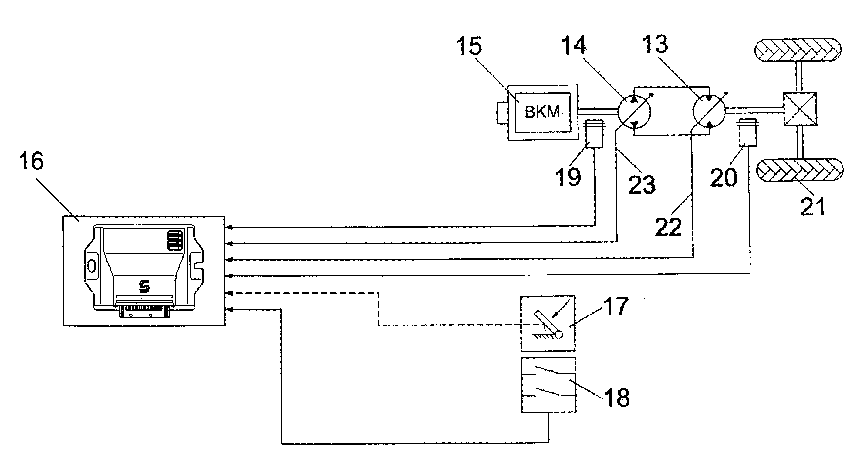
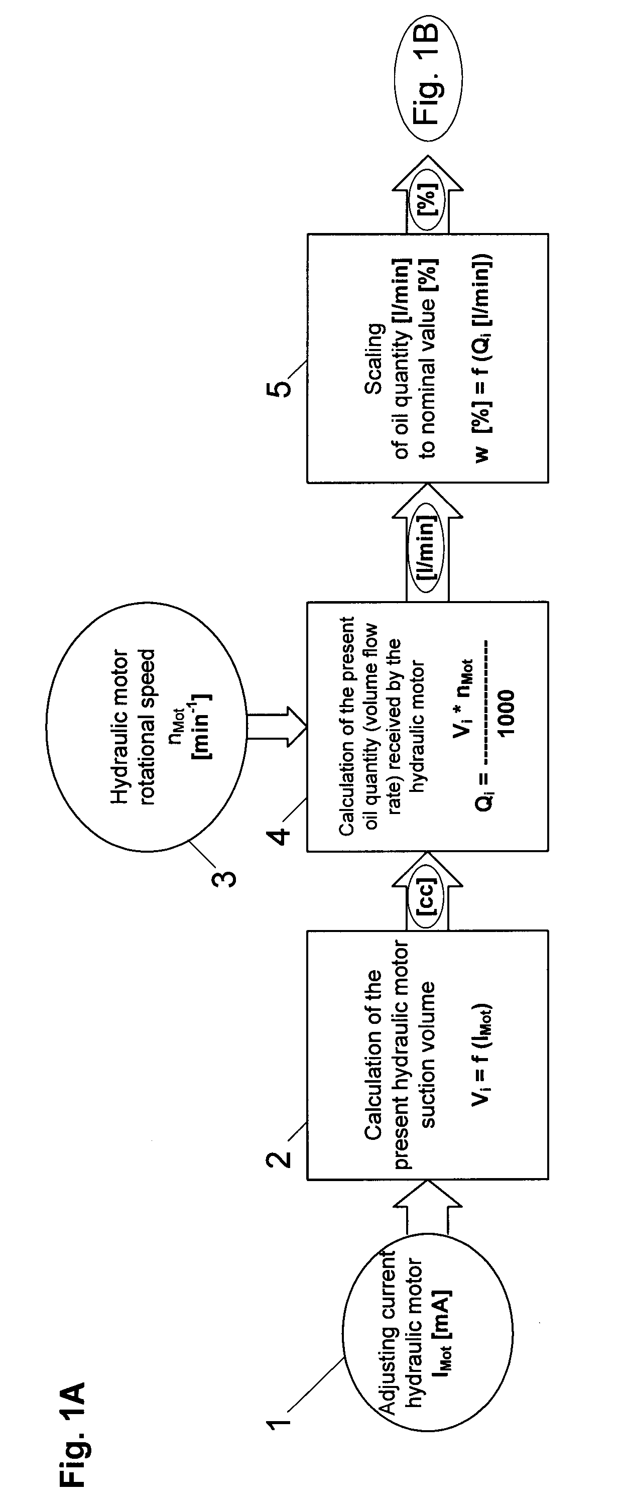
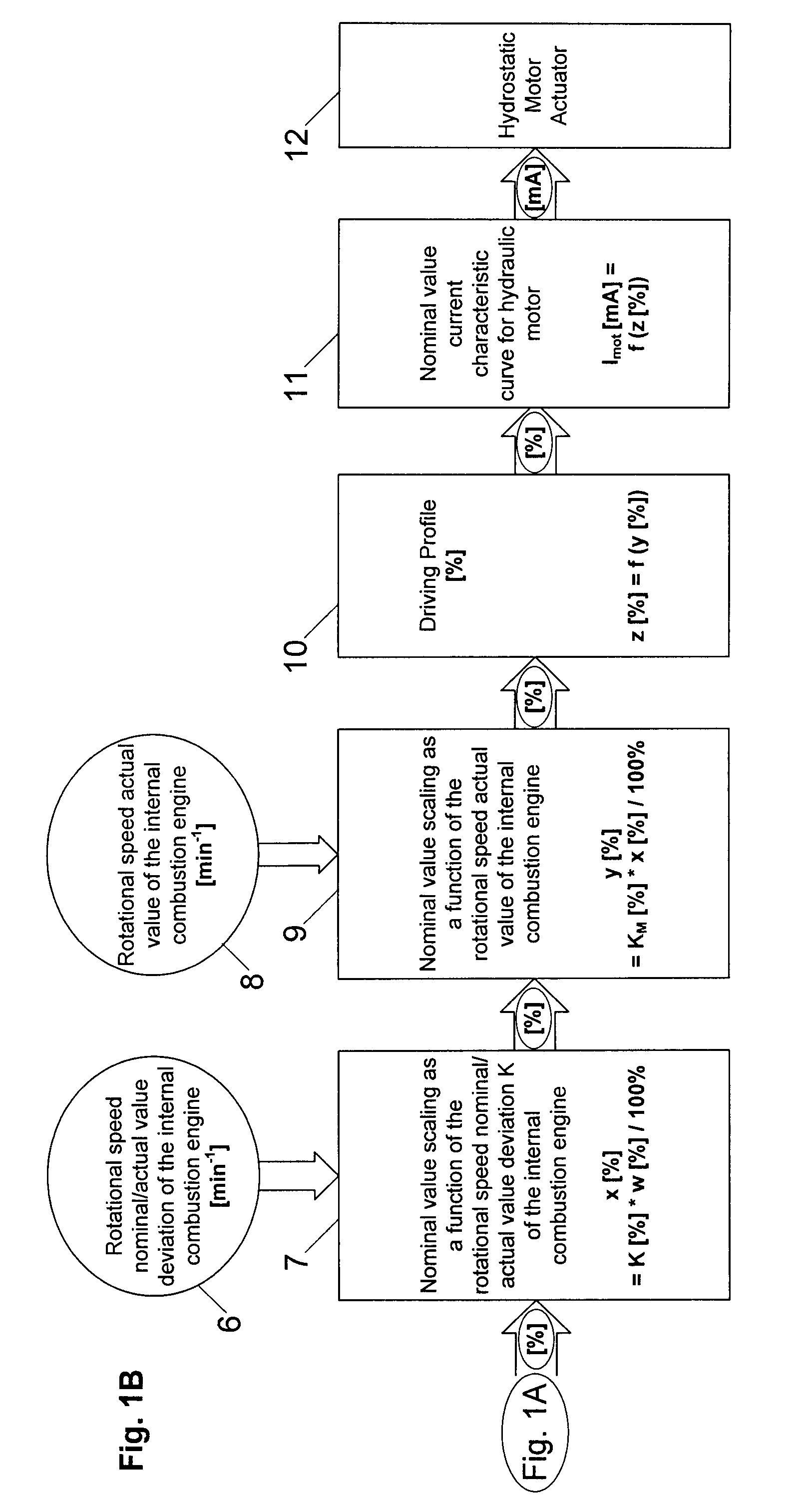
[0020]FIGS. 1A and 1B show the flow diagram of an exemplary embodiment of the flow-regulated hydraulic motor adjustment according to the invention. The regulation is based on the determination of the volume flow rate Q, that is to say the oil quantity which is received by the hydraulic motor as per block 4. In the example illustrated, said oil quantity is determined from the rotational speed nMot and the present suction volume V of the hydraulic motor as per method steps 2, 3. The present suction volume V is in turn given, as per block 1, from the present electrical adjusting current by means of the adjusting current characteristic curve illustrated in FIG. 2. The determined oil quantity Q forms the significant basis for the regulation of the motor adjustment and is converted in block 5 in the course of a simple scaling, as illustrated in FIG. 3, into a first adjustment nominal value w which is specified in percent of the maximum adjustment. This also applies to the further adaptati...


PUM


Abstract

The invention relates to a method for regulating a hydrostatic drive system which has at least one pump which is driven by an internal combustion engine and at least one hydraulic motor which is driven by the pump, and comprises the method steps:
determining the volume flow rate flowing through the hydraulic motor;
determining a first adjustment nominal value for the hydraulic motor as a function of the previously determined volume flow rate rate;
determining a second adjustment nominal value by modifying the first adjustment nominal value by a correction value which is determined as a function of the nominal/actual value deviation of the internal combustion engine rotational speed by means of a vehicle-specific characteristic curve which incorporates the different power profiles for traction and overrun operation, respectively, of the internal combustion engine, with the hydraulic motor being adjusted in such a way that a substantially constant pressure level is generated at the maximum power level of the internal combustion engine.

Description

BACKGROUND OF THE INVENTION[0001]The invention relates to a method for regulating a hydrostatic drive system as per the features of claim 1.[0002]In working and construction machines, hydrostatic travel drives are generally provided, which have an internal combustion engine, typically a diesel engine, at least one pump which is driven by the internal combustion engine and at least one hydraulic motor which is supplied by the pump. Here, the hydraulic motor acts via a step-up gearing or a cardan shaft on the drive axle. The associated travel control actions are often designed to be automotive, that is to say the pivoting-out of the pump takes place as a function of the throttle pedal of the internal combustion engine, and therefore as a function of the rotational speed of the latter. This results in smooth starting and, with a progressive increase in volume flow rate, a rising acceleration of the vehicle. It is therefore possible, in a similar way as in a conventional passenger vehic...

Claims


Application Information

Patent Timeline
Patent Type & Authority Applications(United States)
IPC IPC(8): F16D31/02F16H61/42F16H61/425F16H61/435F16H61/46F16H61/472
CPCF16H61/425F16H61/472F16H61/435
Inventor GERTH, GUNNARBENDIXEN, JAN
Owner SAUER DANFOSS NORDBERG
Why Eureka
Try Eureka