Circular to rectangular waveguide converter including a bend section and mode suppressor

a waveguide converter and rectangular technology, applied in the field of circular waveguides, can solve the problems of reducing the desired signal, introducing problems for circular waveguides, and general complex manufacture of bent waveguides, and achieves excellent rf propagation/loss performance, substantially flat frequency response, and avoid excessive interaction

Active Publication Date: 2008-08-07
EMS TECHNOLOGIES
View PDF10 Cites 24 Cited by
  • Summary
  • Abstract
  • Description
  • Claims
  • Application Information

AI Technical Summary

Benefits of technology

[0009]The inventive circular waveguide bend can interconnect two circular waveguides through a bend and can avoid excessive interaction between the orthogonal modes or polarizations of the circular waveguides. The compact E-plane bend with circular waveguide input and output ports can be achieved, when transmission of only one polarization is required, by providing short quarter wave transformers. The quarter wave transformers can be positioned at the transitions between the circular waveguides and a single-mode quasi-rectangular waveguide segment. Within the single-mode quasi-rectangular waveguide segment, a bend can be formed without concern for mixing of the orthogonal modes of the

Problems solved by technology

Size limitations in satellite applications often demand interconnecting the Fox type phase splitter and the rotary vane attenuator with circular waveguides.
However, the size limitations mentioned above also create a desire to bend the waveguides and effectively fold the circuit into a more compact assembly.
Unfortunately, placing a bend into a circular waveguide can introduces problems.
Bends or discontinuities in the waveguide

Method used


Image

  • Circular to rectangular waveguide converter including a bend section and mode suppressor
  • Circular to rectangular waveguide converter including a bend section and mode suppressor
  • Circular to rectangular waveguide converter including a bend section and mode suppressor

Examples


Embodiment Construction

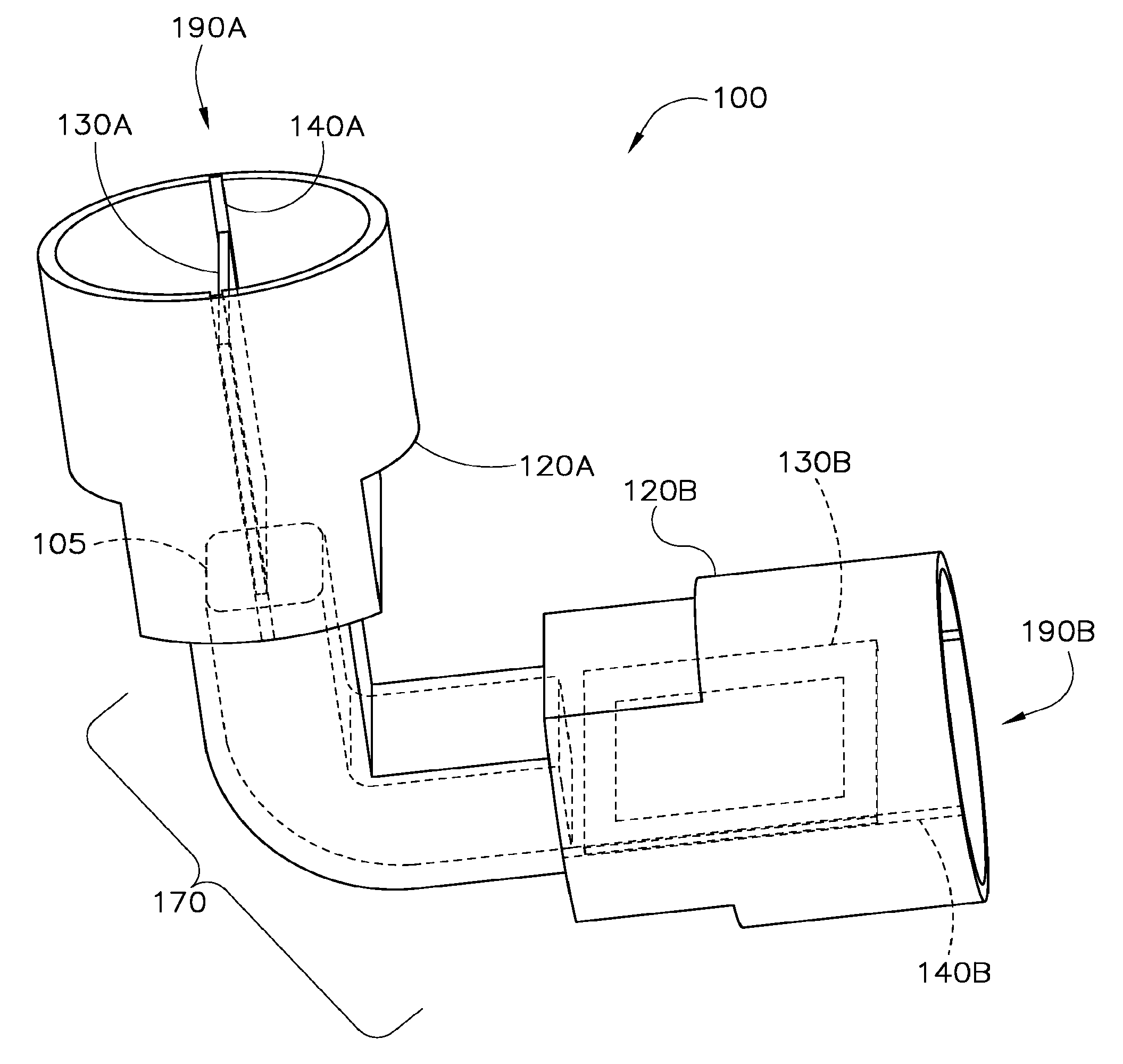
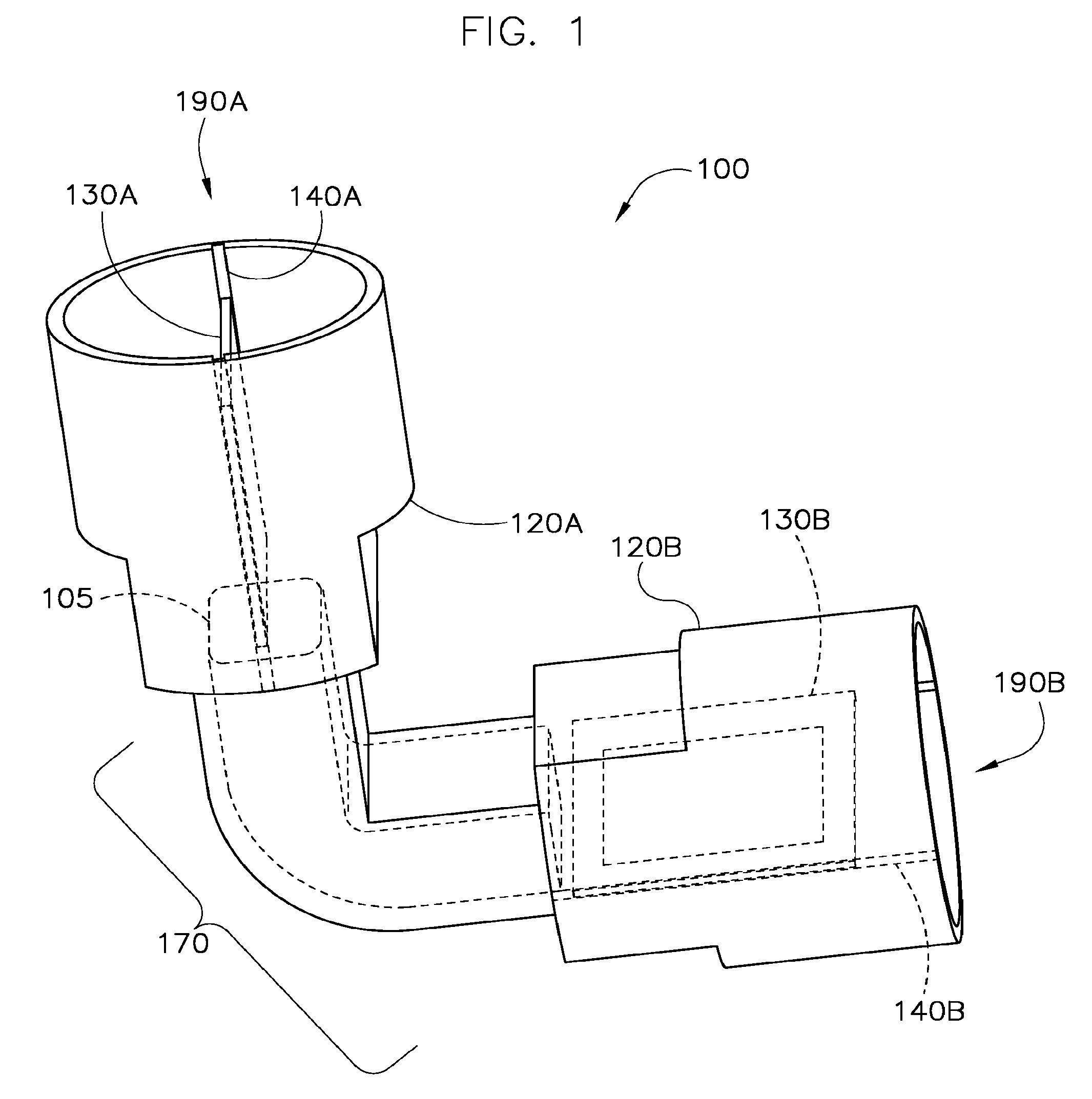
[0019]The invention can include various embodiments, examples of which are described below. One exemplary embodiment can include an E-plane bend between two circular waveguides. Another exemplary embodiment can include an H-plane bend between one circular waveguide and one rectangular wave guide. Other exemplary embodiment can include an E-plane bend between one circular waveguide and one rectangular wave guide as well as a non-bent adapter for coupling a circular waveguide to a traditional rectangular waveguide. Other combinations of straight adapters, E-bends, and H-bends with circular, rectangular, or other waveguide interfaces are not beyond the scope or spirit of the invention.

[0020]Turning now to the drawings, in which like reference numerals refer to like elements, FIG. 1 illustrates a circular waveguide E-bend supporting the interconnection of two circular waveguides according to one exemplary embodiment of the invention. A first circular waveguide (not illustrated) can be c...


PUM


Abstract

A compact circular waveguide system can connect circular waveguides through a bend while avoiding excessive interaction between the orthogonal modes of the circular waveguides. A compact bend system with circular waveguide input and output can be achieved by providing short quarter wave transformers. The quarter wave transformers can be positioned at the transitions between the circular waveguides and a single-mode quasi-rectangular waveguide segment. Within the single-mode quasi-rectangular waveguide segment, a bend can be formed without concern for mixing of the orthogonal modes of the circular guided wave. The undesired mode of propagation can be substantially reduced or eliminated within the quarter wave transformers with a resistive mode suppressor. The compact system can be machined out of a single block of material from the outside flange faces.

Description

PRIORITY CLAIM TO PROVISIONAL APPLICATION[0001]This application claims priority to provisional patent application entitled, “Circular Waveguide E-Bend” filed on Feb. 6, 2006 and assigned U.S. Application Ser. No. 60 / 765,655. The entire contents of the provisional patent application mentioned above are hereby incorporated by reference.TECHNICAL FIELD[0002]The invention is generally directed to circular waveguides for the propagation of electromagnetic energy or signals. The invention relates more specifically to achieving, with high manufacturability, compact bends in circular waveguides for the interconnection of RF (radio frequency) components.BACKGROUND OF THE INVENTION[0003]An electromagnetic waveguide is a structure for conducting electromagnetic waves. Typically these waveguides are rectangular in cross-section, rigid, and constructed of conductive material. Such a waveguide generally serves as an interconnect from one RF component or source to another RF component or load. One...

Claims


Application Information

Patent Timeline
IPC IPC(8): H01P1/02
CPCH01P1/02H01P5/082H01P1/162H01P1/16
Inventor HOOVER, JOHN C.
Owner EMS TECHNOLOGIES
Why Eureka
Try Eureka